
Method and system for partial discharge testing of an insulation component

a technology for partial discharge testing and insulation components, applied in the direction of testing using optic methods, instruments, air-break switches, etc., can solve the problems of partial discharge, electrical breakdown of insulation components, and progressive deterioration

Inactive Publication Date: 2012-08-14
ABB POWER GRIDS SWITZERLAND AG +1
View PDF0 Cites 1 Cited by
  • Summary
  • Abstract
  • Description
  • Claims
  • Application Information

AI Technical Summary

Benefits of technology

[0027]The generated partial discharges hence being natural partial discharges can have an the advantage that the employed partial discharge equipment or apparatus can be of lower precision and can work with less noise reduction than devices that are used for partial discharge detection under permanent X-ray irradiation. On the other hand even smaller voids can be detected if a given device with its inherent noise reduction is employed. It is another exemplary advantage that well established rules can be used for interpretation of the results.

Problems solved by technology

Dielectrics of the insulation component can, however, exhibit regions of high electric field intensity which may cause partial discharges that are characterized in that they do not completely bridge the electrodes.
The partial discharges can then cause progressive deterioration of the material of the insulation component which ultimately might lead to an electrical breakdown of the insulation component.
This means, that even in the case of voids being present, they may not be detected due to a lack of free electrons in or at the void or due to a statistical time lag, being the time required for a free electron to appear in the void.
In particular, small voids may not develop partial discharge activity within the duration of the known partial discharge test and therefore may not be detected.
Known partial discharge tests often use very high AC voltages, which leads to field emission from the void surface, to force also the small voids into discharge.
However, using such high AC voltage may cause irreversible damage by initiating electrical trees from other stressed enhancing defects, such as inclusions of metallic particles which might have been harmless at operating stress.
Such high precision, low noise partial discharge detection equipment is, however, not suitable for usage in a factory environment.

Method used


Image

  • Method and system for partial discharge testing of an insulation component
  • Method and system for partial discharge testing of an insulation component
  • Method and system for partial discharge testing of an insulation component

Examples


Embodiment Construction

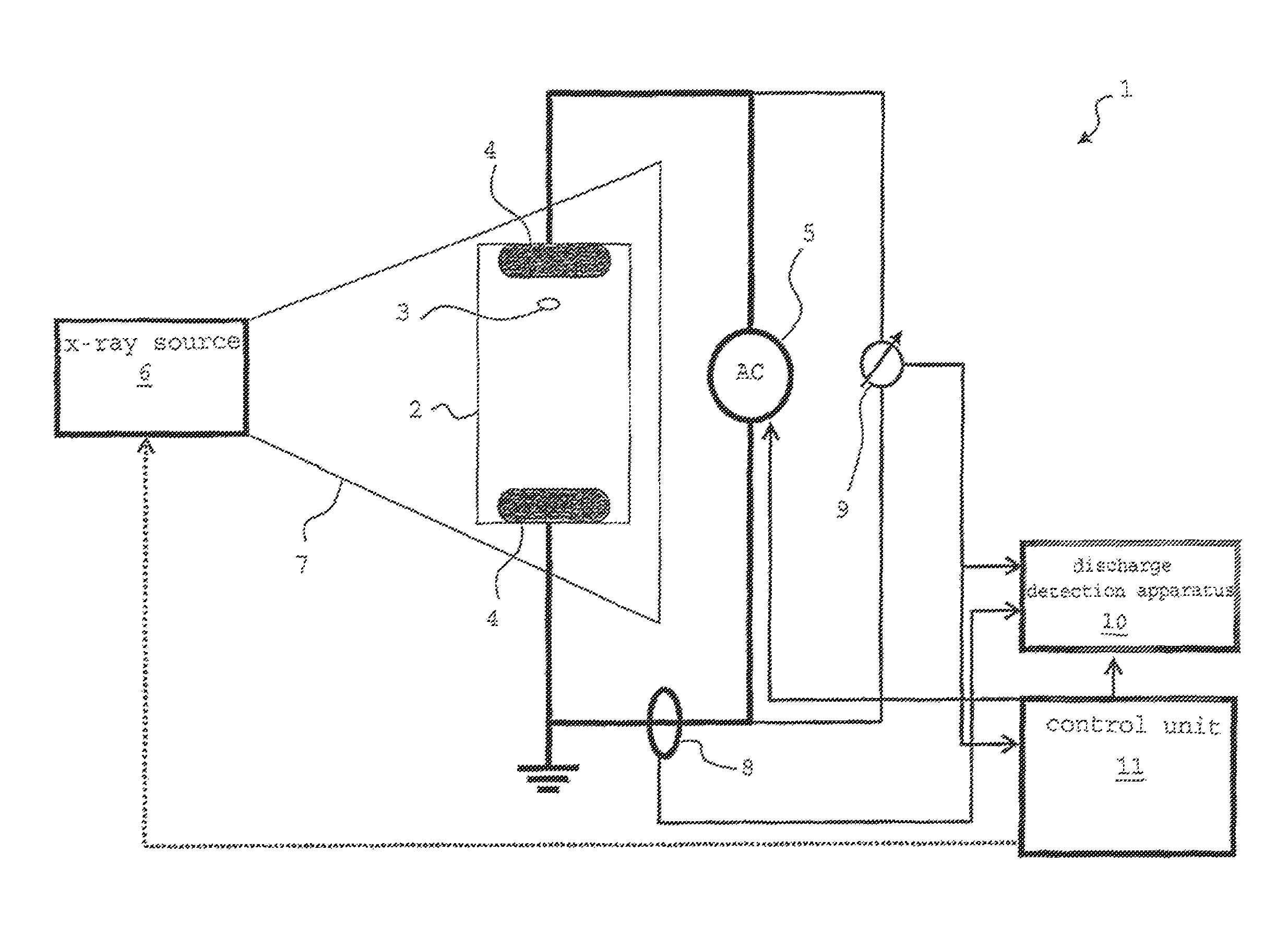
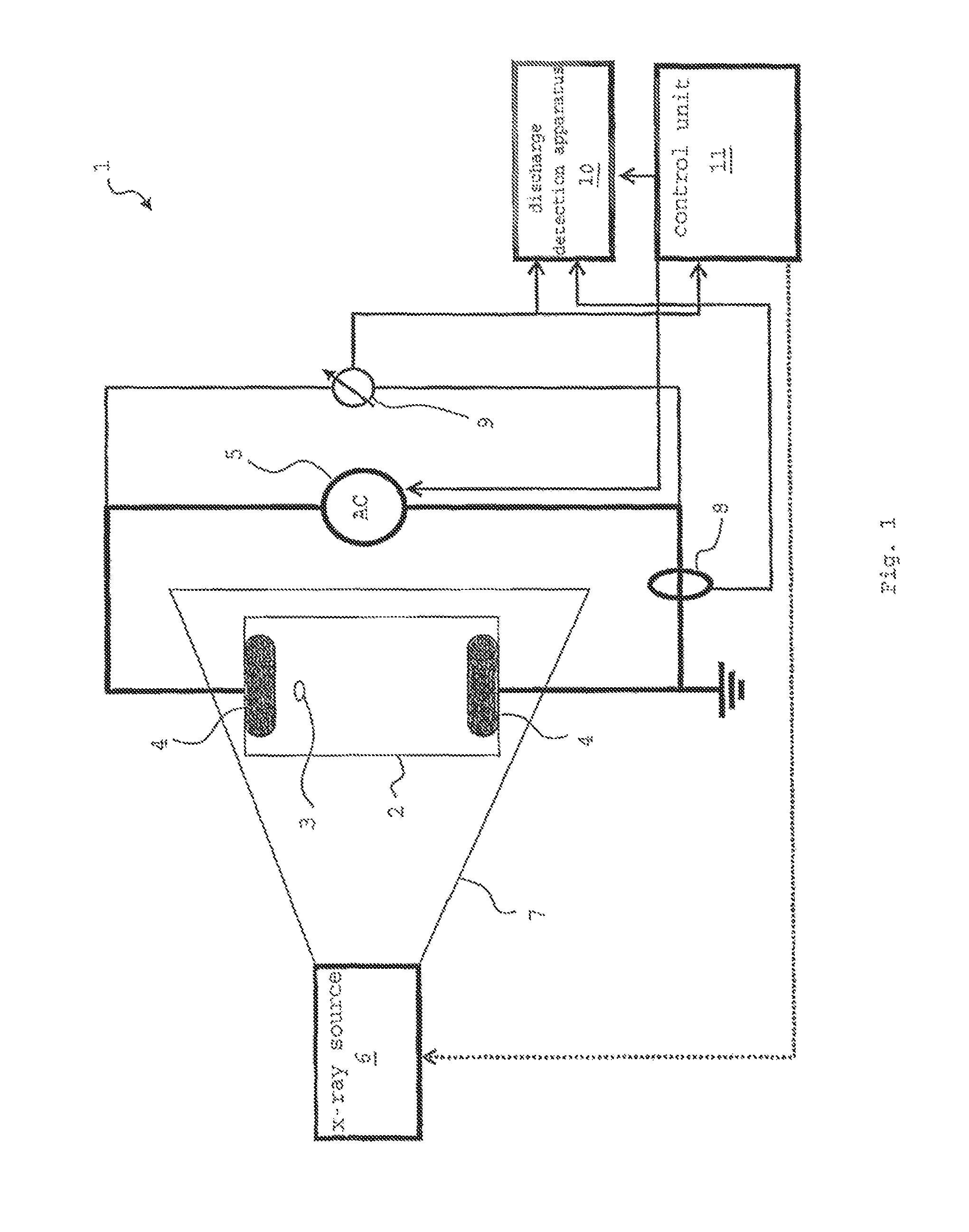
[0020]A method and a system are disclosed for partial discharge testing of an insulation component by which voids of the insulation component can be easily detected. An exemplary method and a system for partial discharge testing of an insulation component are provided by which the inception voltage of the partial discharges can be lowered while the dynamic behaviour of the partial discharges (and of the electron avalanches within the void causing the partial discharge) basically remains preserved when compared to the known tests and systems without radiation.

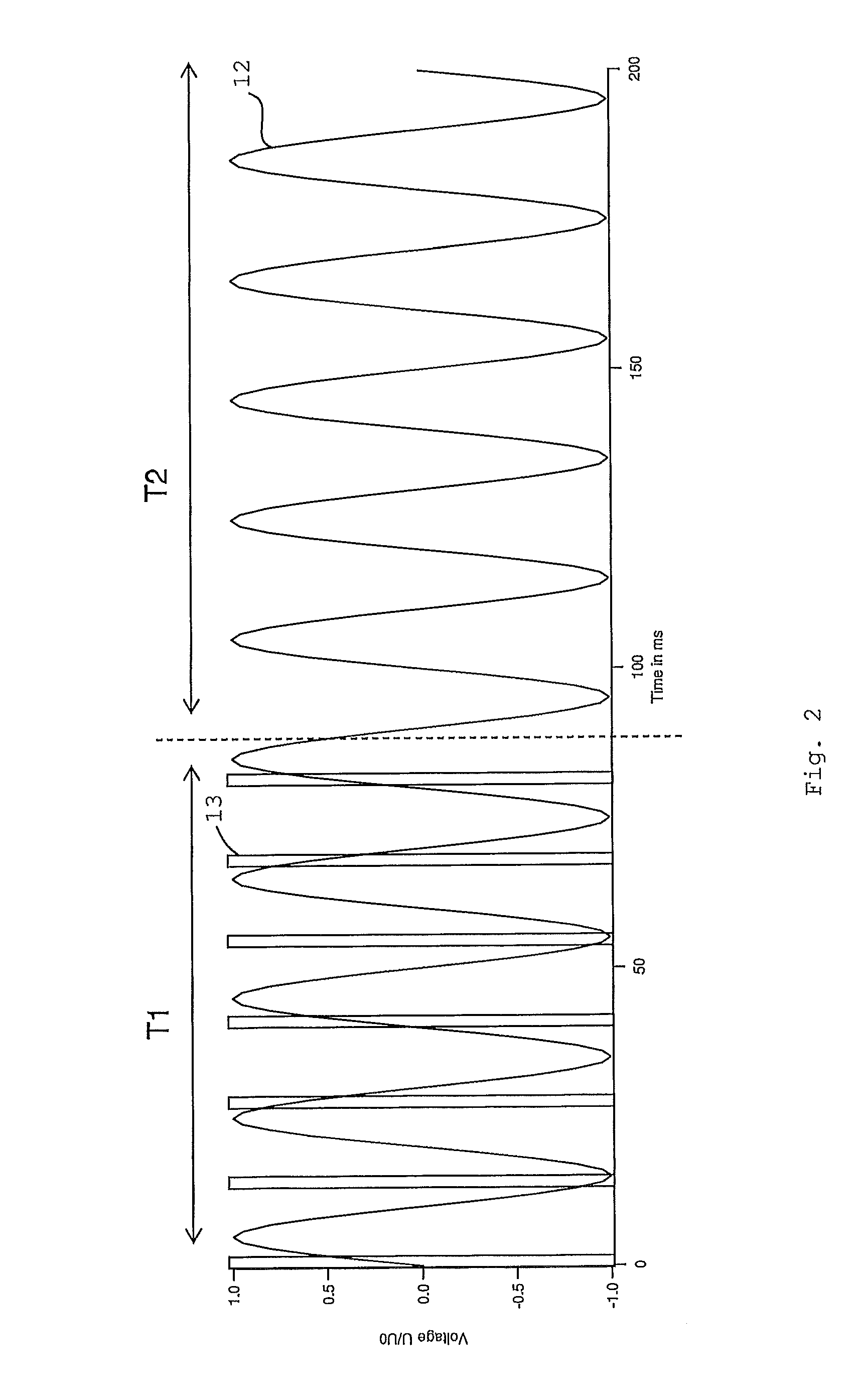
[0021]In an exemplary method for partial discharge testing of an insulation component, an AC voltage is applied to the insulation component and at least one X-ray pulse with a radiation dose rate of equal to or more than about (e.g., plus or minus 10%) 10−2 Gray / s (10 mGray / s), and, for example, of a duration of less than about 1 ms, is applied to the insulation component and the partial discharge induced by the at least one X-r...


PUM


Abstract

The disclosure relates to a method for partial discharge testing of an insulation component, wherein at least one X-ray pulse is applied to the insulation component, an AC voltage is applied to the insulation component and the partial discharge induced by the at least one X-ray pulse is measured, wherein the dose rate of the at least one X-ray pulse is at least about 10−2 Gray / s. The disclosure relates further to a system for partial discharge testing of an insulation component which includes a flash X-ray source for generating at least one X-ray pulse, an AC voltage source, a voltage sensor, a partial discharge sensor and a partial discharge detection device for evaluating the measured partial discharge.

Description

RELATED APPLICATION[0001]This application claims priority under 35 U.S.C. §119 to European Patent Application No. 08162742.4 filed in Europe on Aug. 21, 2008, the entire content of which is hereby incorporated by reference in its entirety.FIELD[0002]The disclosure relates to a method and system for partial discharge testing of an insulation component. The insulation component can, for example, include (e.g., consist of) solid dielectric material, such as filled epoxy resin, but is not limited to being solid.BACKGROUND INFORMATION[0003]Insulation components are used in high voltage electrical equipment, such as for example capacitors, transformers or switchgear barriers. Dielectrics of the insulation component can, however, exhibit regions of high electric field intensity which may cause partial discharges that are characterized in that they do not completely bridge the electrodes.[0004]The partial discharges quite often start, for example, within inhomogeneities such as voids or cra...

Claims


Application Information

Patent Timeline
Patent Type & Authority Patents(United States)
IPC IPC(8): G01R31/02
CPCG01R31/1218G01R31/1245G01R31/1272G01R31/12
Inventor FUHRMANN, HENNINGKRIVDA, ANDREJ
Owner ABB POWER GRIDS SWITZERLAND AG
Learn More