
Door lock control device

a control device and door lock technology, applied in the direction of securing communication, electric devices, program control, etc., can solve the problems of adversely affecting other circuits or antennas, large amount of power consumed by the power source of the vehicle, etc., to prevent the unnecessary power supply to the operation reception unit, inhibit power consumption, and inhibit an adverse

Active Publication Date: 2012-08-14
TOYOTA JIDOSHA KK
View PDF8 Cites 3 Cited by
  • Summary
  • Abstract
  • Description
  • Claims
  • Application Information

AI Technical Summary

Benefits of technology

Reduces unnecessary power consumption and minimizes radiation interference with other circuits by stopping power supply to sensors when an occupant is present, thereby optimizing energy use and reducing electromagnetic interference.

Problems solved by technology

In the door lock control device described in JP-A-2006-9312 electric power is constantly supplied from a power source to the lock control sensor (general name of the lock sensor and unlock sensor) and, therefore, a large amount of power of the power source of the vehicle is consumed.
Furthermore, because the power is constantly supplied to the lock control sensors, radiation is constantly emitted from the sensor circuit and this radiation can adversely affect other circuits or antenna.

Method used


Image

  • Door lock control device
  • Door lock control device
  • Door lock control device

Examples


Embodiment Construction

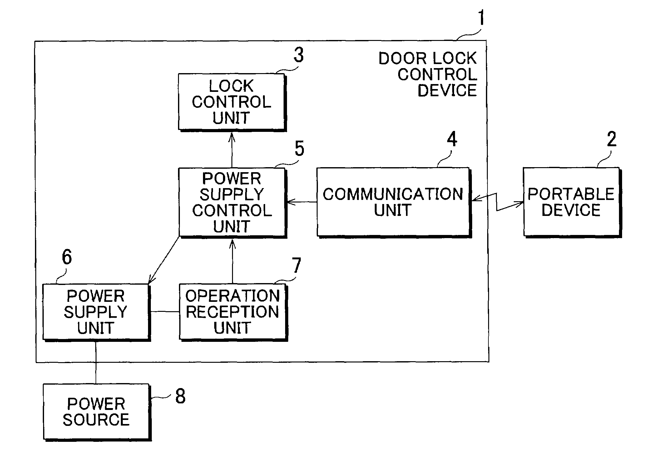
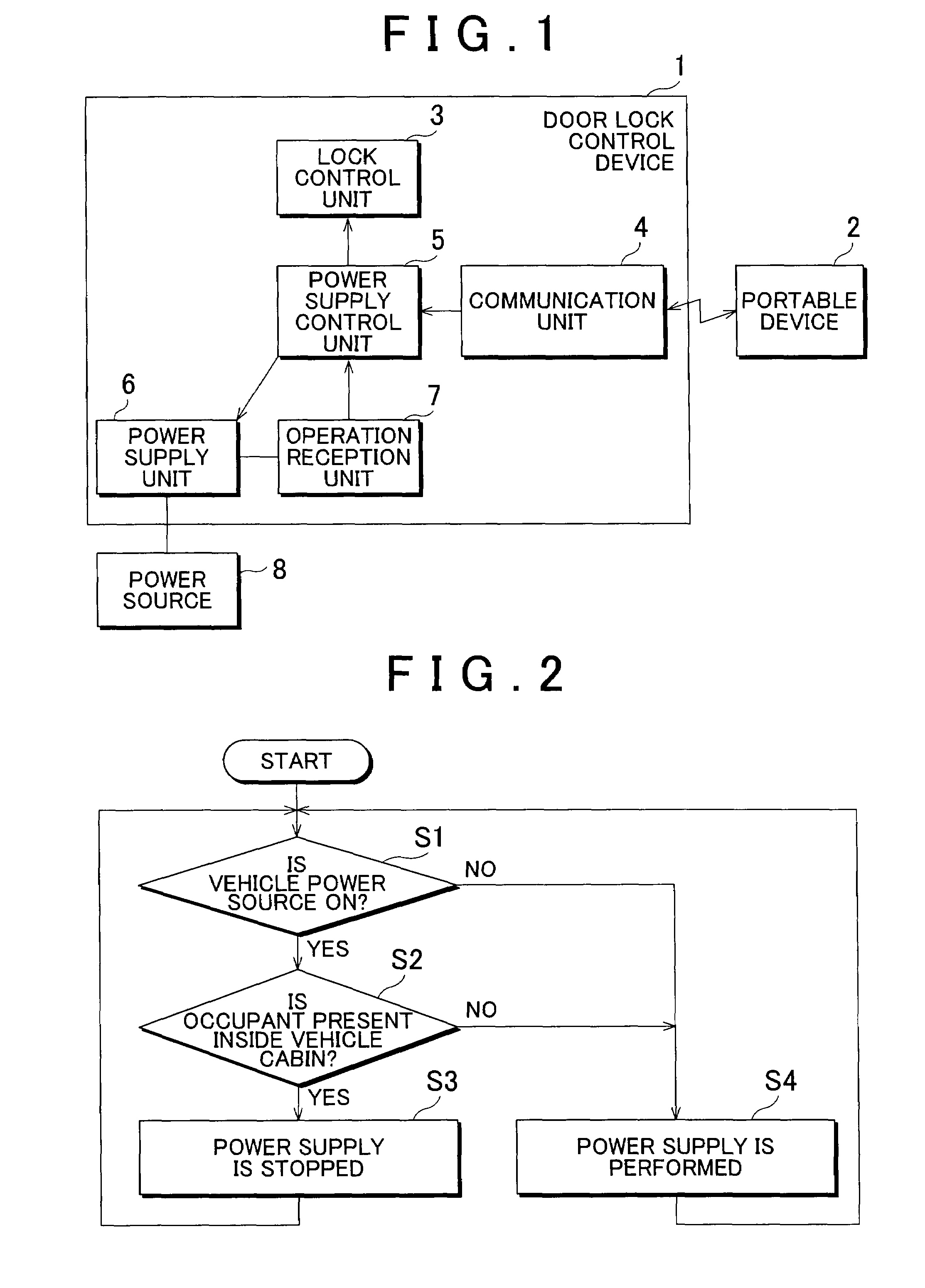
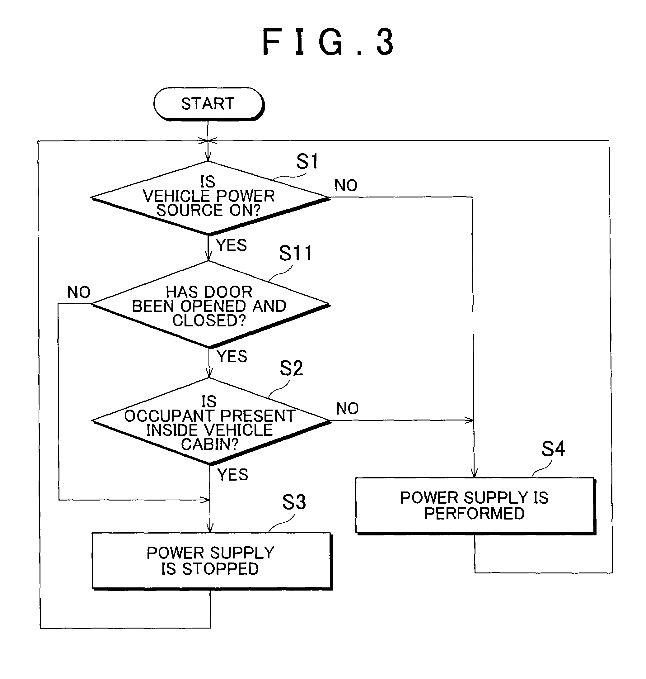
[0020]The door lock control device on an embodiment of the invention will be described below with reference to FIGS. 1 and 2. FIG. 1 is a block diagram illustrating a functional configuration of a door lock control system including the door lock control device on the present embodiment. Referring to FIG. 1, the door lock control system includes the door lock control device 1 of the present embodiment and a portable device 2 that can communicate with the door lock control device 1. The door lock control system shown in FIG. 1 controls locking and / or unlocking of a vehicle door. More specifically, the present door lock control system is one of the so-called smart key systems such that a vehicle door can be locked or unlocked, provided that the door lock control device 1 installed on the vehicle has communicated with a portable device 2 and the portable device 2 has been confirmed to be a valid key. As a result, only a valid user that has the valid portable device 2 can perform the doo...


PUM


Abstract

A door lock control device that performs locking and / or unlocking of a door of a vehicle subject to a condition that a result of communication with a portable device has authenticated the portable device. The door lock control device has: an operation reception unit that is provided in the vehicle and receives an input for instructing the locking and / or unlocking of the door; a vehicle power source determination unit that determines whether a power source of the vehicle is ON; an occupant determination unit that determines whether an occupant is present in a cabin of the vehicle; and a power supply control unit that stops power supply to the operation reception unit when determination is made that the power source of the vehicle is ON and an occupant is present inside the vehicle cabin.

Description

INCORPORATION BY REFERENCE[0001]The disclosure of Japanese Patent Application No. 2008-014034 filed on Jan. 24, 2008 including the specification, drawings and abstract is incorporated herein by reference in its entirety.BACKGROUND OF THE INVENTION[0002]1. Field of the Invention[0003]The invention relates to a door lock control device, and more particularly to a door lock control device that controls door locking and / or unlocking correspondingly to an input result into an input unit provided in a vehicle subject to the condition that a portable device is present within a detection area around the vehicle.[0004]2. Description of the Related Art[0005]A technology for controlling door locking / unlocking correspondingly to a detection result of a touch sensor provided in a vehicle subject to the condition that a portable device is present within detection area around the vehicle has heretofore been suggested. For example, Japanese Patent Application Publication No. 2006-9312 (JP-A-2006-93...

Claims


Application Information

Patent Timeline
Patent Type & Authority Patents(United States)
IPC IPC(8): B60R25/00B60R25/01B60R25/24B60R25/31B60R25/40E05B49/00
CPCB60R25/20B60R25/305
Inventor MURAKAMI, HIROKO
Owner TOYOTA JIDOSHA KK
Learn More