Method and apparatus for detecting targets through temporal scene changes

a temporal scene and target detection technology, applied in the field of computer vision systems, can solve the problems of multispectral image analysis techniques for shadow detection, image noise in transformed color space is higher than that in original image data, and the background model cannot be buil

Active Publication Date: 2012-08-14
SRI INTERNATIONAL
View PDF14 Cites 11 Cited by
  • Summary
  • Abstract
  • Description
  • Claims
  • Application Information

AI Technical Summary

Problems solved by technology

Unfortunately, a background model cannot be built when there is little overlap between one image and the next image, such as from airborne imagery.
However, image noise in transformed color space tends to be higher compared to that in the original image data.
Multispectral image analysis techniques for shadow detection, such as described in U.S. Pat. No. 7,184,890, cannot be directly applied to single spectral images as these techniques exploit the characteristics of individual spectra in information integration.
The prior art generally relies on heuristics or static background / scene knowledge that render existing change-based target detection systems “brittle,” i.e., such systems are likely to fail in an unexpected manner when deviations from the heuristics or background knowledge are large.

Method used


Image

  • Method and apparatus for detecting targets through temporal scene changes
  • Method and apparatus for detecting targets through temporal scene changes
  • Method and apparatus for detecting targets through temporal scene changes

Examples


Embodiment Construction

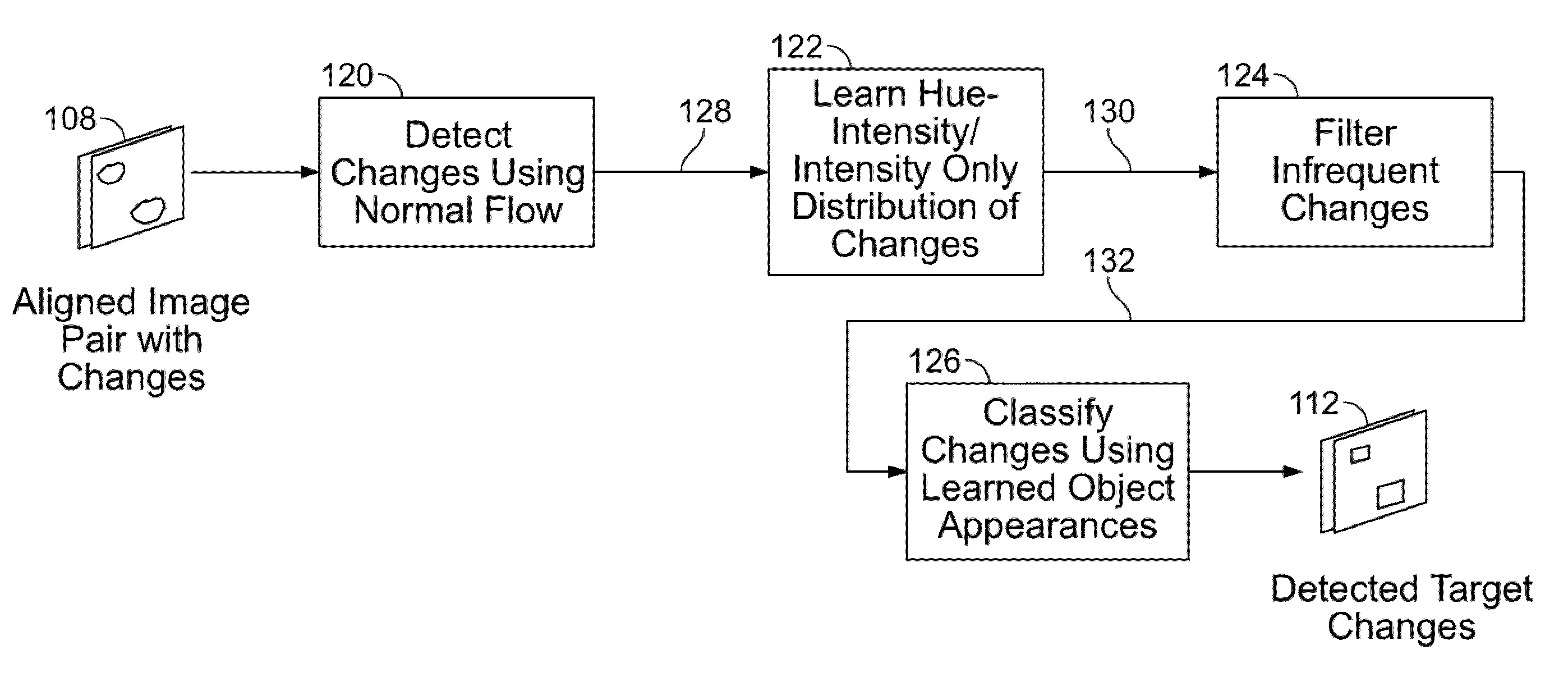
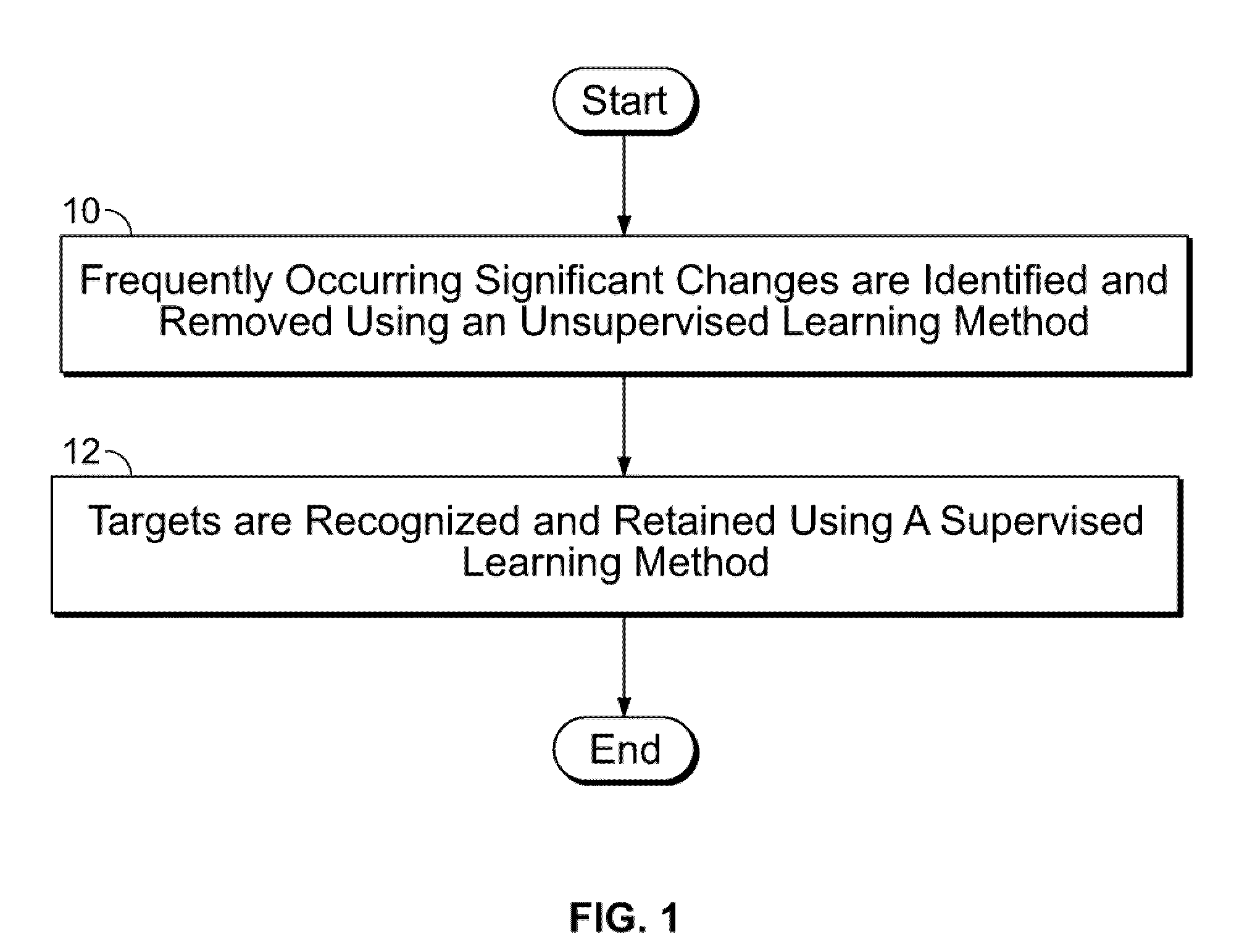
[0031]FIG. 1 is a high-level process flow diagram illustrating exemplary steps for detecting targets in imagery, according to an embodiment of the present invention. At step 10, frequently occurring significant changes, such as due to shadows, are identified and removed using an unsupervised learning method. The unsupervised method “learns” to distinguish true changes from clutter in an unsupervised manner. At step 12, changes of interest are recognized and retained of using a supervised learning method. The supervised method learns to detect specific types of objects in a supervised manner.

[0032]As used herein, the term “supervised learning” refers to an entity that “teaches” what an object looks like, i.e., an entity or process that provides positive and negative samples of an object for training purposes. For example, a classifier may be trained to determine what a car looks like by providing positive samples of cars and negative samples of objects which are not cars. In an “unsu...


PUM


Abstract

A system and method for detecting a target in imagery is disclosed. At least one image region exhibiting changes in at least intensity is detected from among at least a pair of aligned images. A distribution of changes in at least intensity inside the at least one image region is determined using an unsupervised learning method. The distribution of changes in at least intensity is used to identify pixels experiencing changes of interest. At least one target from the identified pixels is identified using a supervised learning method. The distribution of changes in at least intensity is a joint hue and intensity histogram when the pair of images pertain to color imagery. The distribution of changes in at least intensity is an intensity histogram when the pair of images pertain to grey-level imagery.

Description

CROSS-REFERENCE TO RELATED APPLICATIONS[0001]This application claims the benefit of U.S. provisional patent application No. 61 / 073,212 filed Jun. 17, 2008, the disclosure of which is incorporated herein by reference in its entirety.GOVERNMENT RIGHTS IN THIS INVENTION[0002]This invention was made with U.S. government support under contract number HR0011-06-C-0018. The U.S. government has certain rights in this invention.FIELD OF THE INVENTION[0003]The present invention relates generally to computer vision systems, and more particularly, to a method and system for detecting targets in video and images based on temporal scene changes of the targets.BACKGROUND OF THE INVENTION[0004]In recent years, an active area of research has been foreground object detection. A common method for detecting foreground objects or objects of interest (“targets” in military jargon) in a sequence of time-ordered images / video is through change / anomaly detection in images / video (or “imagery”). Foreground obj...

Claims


Application Information

Patent Timeline
Patent Type & Authority Patents(United States)
IPC IPC(8): G06K9/00G06V10/50
CPCG06K9/3241G06K9/4642G06K9/6857G06V10/255G06V10/50G06V30/2504
Inventor DAS, SUBHODEVTAN, YICHIU, MING-YEECOPPOCK, ANDREWHAN, FENG
Owner SRI INTERNATIONAL
Why Eureka
Try Eureka