Wall framing stud and wall framing system

a wall framing system and wall framing technology, applied in the field of wall framing, can solve the problems of inefficiency of wall framing systems in several respects

Active Publication Date: 2012-08-21
INNOVATIVE BUILDING CONCEPTS
View PDF20 Cites 6 Cited by
  • Summary
  • Abstract
  • Description
  • Claims
  • Application Information

AI Technical Summary

Benefits of technology

[0010]The present invention is a framing unit having universal framing applications that can complete all of the fourteen framing tasks listed above—both as a framing stud and a framing plate or track. The universal framing unit is smaller in width and depth than a full dimension framing stud (i.e. one that spans the entire depth of a wall or partition) and includes a slot configuration on both ends thereof. The present universal framing unit provides flexibility in manipulation thus providing flexibility in framing.
[0012]The first and second slots of one or both ends of the universal framing unit are preferably, but not necessarily, wider at the end(s) of the framing unit to provide configured slots (see e.g. FIGS. 1-5). Such width is provided by an angled cut, notch or cutout that extends from an end of the respective lateral side wall to the slot. This allows the framing unit ends to be slid easily over the walls of the universal framing unit used as a plate (see, e.g. FIGS. 1-6). The slots allow the universal framing unit to be extended to meet the ceiling heights.
[0013]In one form, the universal framing unit as a framing stud is much smaller than standard studs, measuring 1½″ one direction and 1″ in the other direction but comes in the same lengths that standard studs come in (e.g. eight and ten feet). In the middle of the 1½″ side and at each end of the universal unit is preferably, but not necessarily, a pre-drilled hole (see, e.g. FIGS. 1-3) in order to make it user friendly to screw the universal framing unit as a stud to the universal framing unit as a plate (see, e.g. FIGS. 1-7). Along each open side of the universal framing unit, the metal is hemmed over (see, e.g. FIGS. 1-4) to both give the universal framing unit strength and leave smooth edges along which the wiring run without the wiring being cut.

Problems solved by technology

Presently, the art of wall framing systems is rendered inefficient in several respects.
Many of these inefficiencies arise from the limitations of the standard “C” stud as well as other prior art studs and / or stud systems.

Method used


Image

  • Wall framing stud and wall framing system
  • Wall framing stud and wall framing system
  • Wall framing stud and wall framing system

Examples


Embodiment Construction

[0032]For the purpose of promoting an understanding of the principles of the invention, reference will now be made to the embodiment illustrated herein and specific language will be used to describe the same. It will nevertheless be understood that no limitation of scope of the invention is thereby intended, such alterations, modifications, and further applications of the principles of the invention being contemplated as would occur to one skilled in the art to which the invention relates.

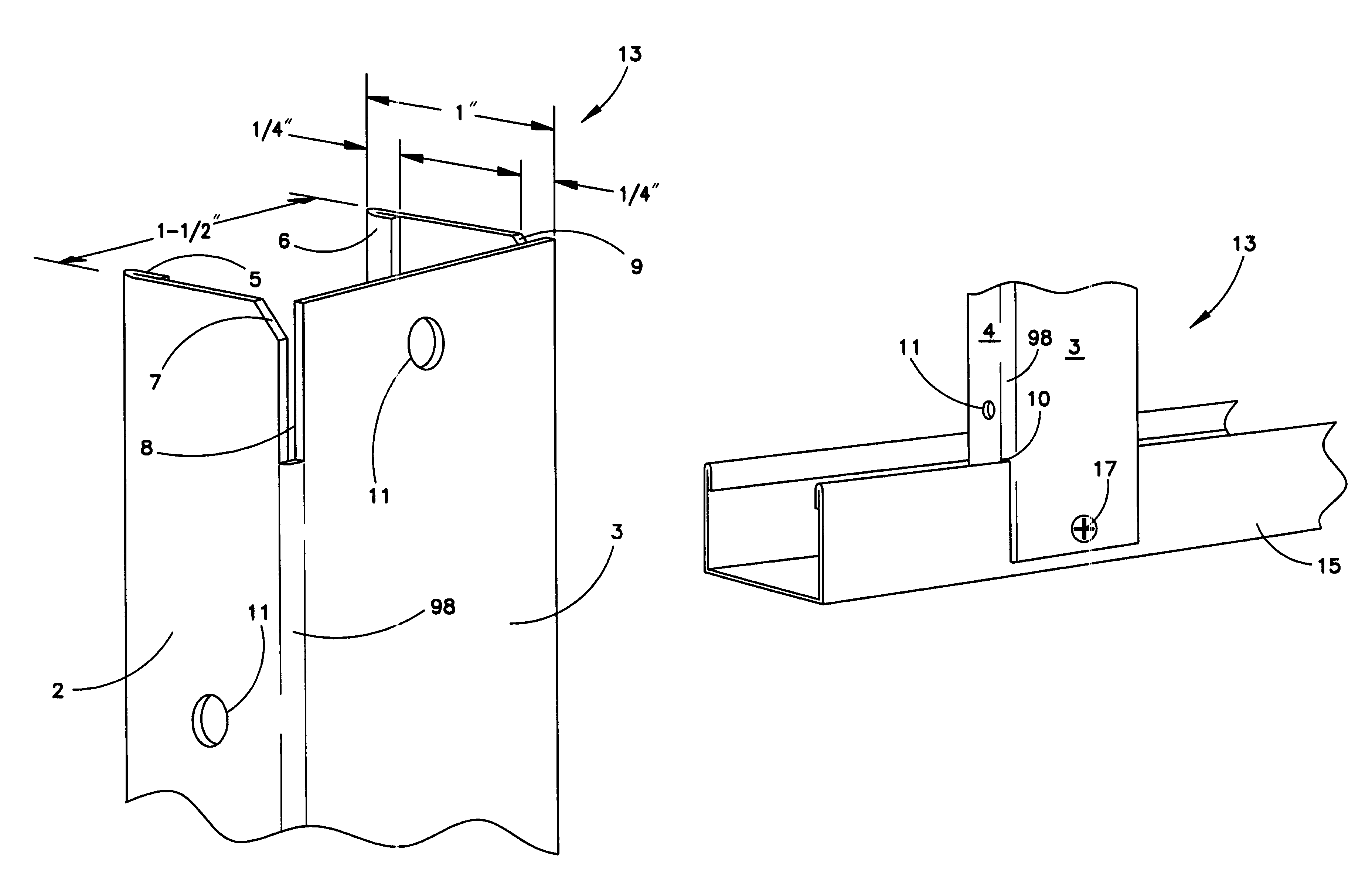
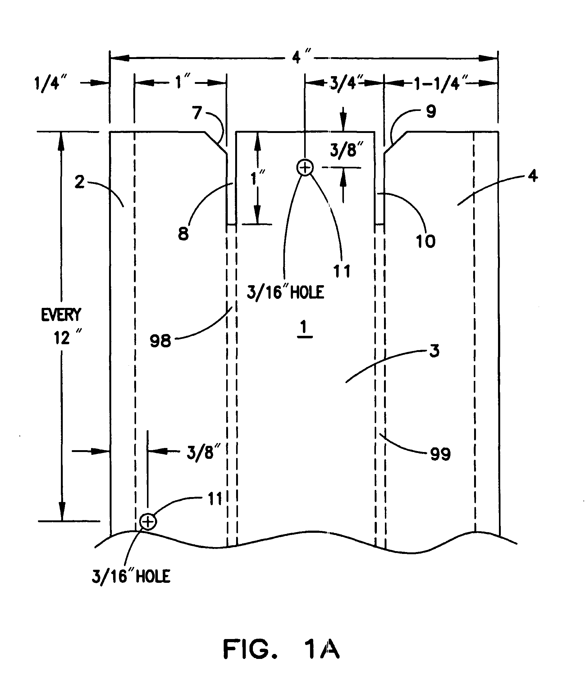
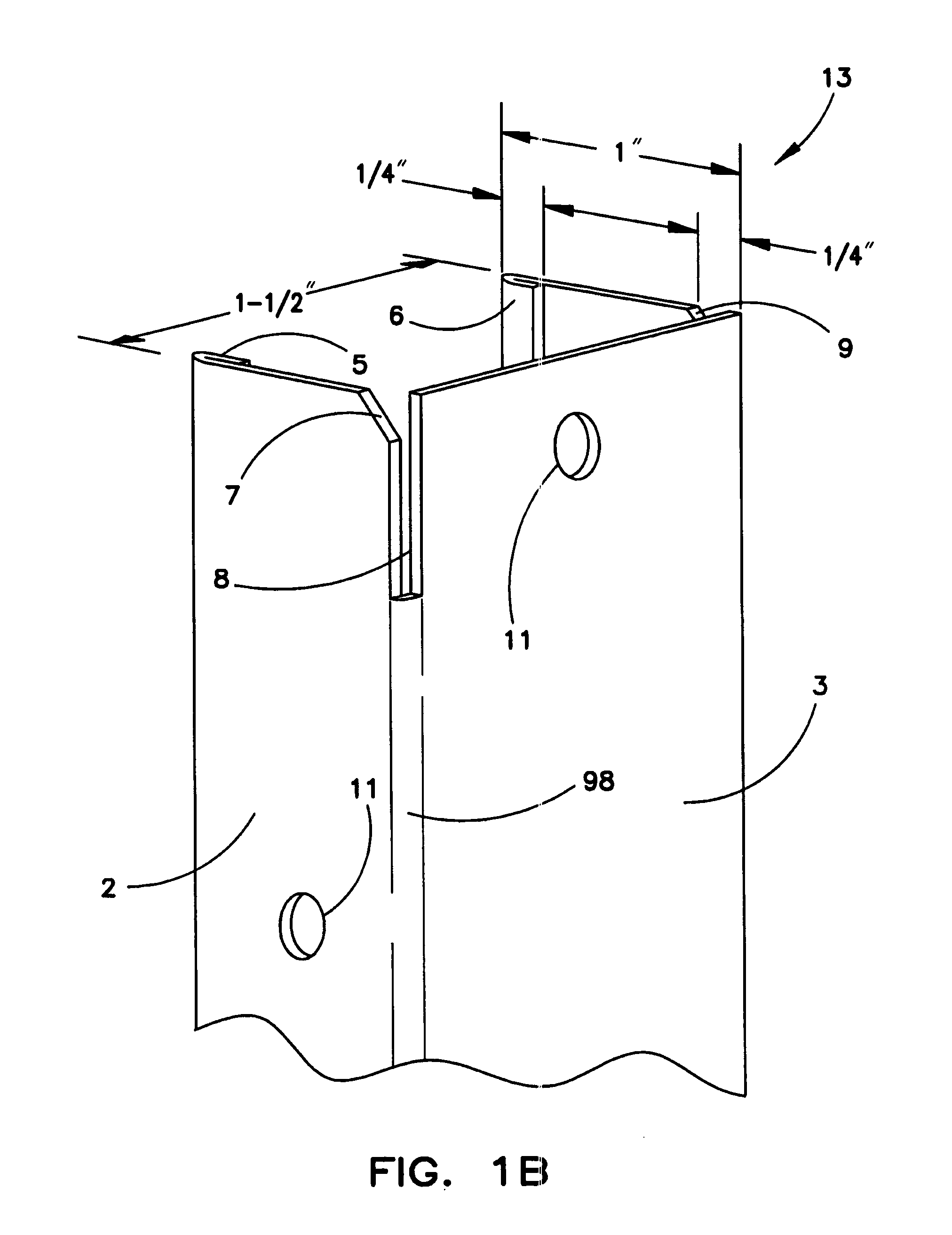
[0033]A multitude of framing and / or bracing jobs are solved by having the present universal framing / bracing (collectively, framing) unit on the job site. A framing system utilizing the universal framing unit includes just one type of unit that doubles as a stud and as a plate or track—i.e. the present universal framing unit. The universal framing unit has two flanged sides with mended edges and slots at each end that provides connection to a base plate. These slots are used to interlock the univers...


PUM


Abstract

A framing system for a new or existing wall, structure and / or the like is provided that uses just one type of unit or member for various framing applications, namely serving as a framing stud and framing plate or track—i.e. a universal framing unit. The universal framing unit is formed from a single piece of metal as a three-wall member having a front wall, a first lateral wall, and a second lateral wall. The first lateral wall is continuous with a first lateral side of the front wall via a first curved transition so as to be generally perpendicular relative to the front wall, while the second lateral wall is continuous with a second lateral side of the front wall via a second curved transition so as to be generally perpendicular relative to the front wall. A first slot is formed in the first curved transition and extends from a first end of the universal framing unit a first length along the first curved transition. A second slot is formed in the second curved transition and extends from the first end of the universal framing unit a second length along the second curved transition. A notch may be provided at the junction of the slot and the respective lateral wall to create a wider entrance to the slot. Preferably, the second end of the universal framing unit has the same first and second slot configurations in the first and second curved transitions.

Description

RELATED APPLICATIONS[0001]This patent application is a continuation-in-part of U.S. patent application Ser. No. 12 / 190,305 filed Aug. 12, 2008 now abandoned entitled “Universal Stud” which was a continuation of now abandoned U.S. patent application Ser. No. 11 / 199,502 filed Aug. 9, 2005 entitled “Universal Stud” which claims, and thus this application claims, the benefit of and / or priority to U.S. Provisional Patent Application Ser. No. 60 / 591,371 entitled “Universal Stud” the entire contents of all of which is specifically incorporated herein by this reference.BACKGROUND OF THE INVENTION[0002]1. Field of the Invention[0003]The present invention relates generally to the field of wall framing and particularly to specific areas and jobs of framing that the ordinary “C” stud has a problem doing or can not do physically.[0004]2. Background Information[0005]Presently, the art of wall framing systems is rendered inefficient in several respects. Many of these inefficiencies arise from the ...

Claims


Application Information

Patent Timeline
Patent Type & Authority Patents(United States)
IPC IPC(8): E04H5/00
CPCE04B2/7457E04B2/767E04C3/07E04B2/7409E04B2002/7488E04C2003/0473
Inventor WRIGHT, WILLIAM ARTHUR
Owner INNOVATIVE BUILDING CONCEPTS
Why Eureka
Try Eureka