
Sub-frame mount for suspension

a subframe and suspension technology, applied in the direction of roofs, jet propulsion mounting, transportation and packaging, etc., can solve the problems of increased inability to delay or alleviate the impact force transmitted to the vehicle body through the subframe, and riders' injuries, so as to improve the mounting structure of the subframe and reduce the deceleration of the vehicle body

Active Publication Date: 2012-08-21
HYUNDAI MOTOR CO LTD +1
View PDF16 Cites 19 Cited by
  • Summary
  • Abstract
  • Description
  • Claims
  • Application Information

AI Technical Summary

Benefits of technology

The present invention provides a sub-frame mount for a suspension that improves the mounting structure of the sub-frame to the vehicle body and reduces deceleration of the vehicle body in a head-on collision. The mount includes a frame structure with front and rear mounting portions connected to the vehicle body through mount bolts. The rear mounting portion has three holes, including a first hole in the upper plate, a second hole in the lower plate, and a third hole connected to the second hole. A spacer is placed between the upper and lower plates, and a cross-sectional shape of the spacer is U-shaped to support the body of the second mount bolt. The first hole is a slot, and the second and third holes are connected to form a T-shape hole. The technical effects of the invention include improved mounting structure and reduced deceleration of the vehicle body in a head-on collision.

Problems solved by technology

However, since the mount bolt is fixed to the vehicle body, deceleration of the vehicle body becomes increase.
As the deceleration of the vehicle body increases, the impact force transmitted to the vehicle body through the sub-frame cannot be delayed or alleviated.
Therefore, riders may be injured.

Method used


Image

  • Sub-frame mount for suspension
  • Sub-frame mount for suspension
  • Sub-frame mount for suspension

Examples


Embodiment Construction

[0030]Reference will now be made in detail to various embodiments of the present invention(s), examples of which are illustrated in the accompanying drawings and described below. While the invention(s) will be described in conjunction with exemplary embodiments, it will be understood that present description is not intended to limit the invention(s) to those exemplary embodiments. On the contrary, the invention(s) is / are intended to cover not only the exemplary embodiments, but also various alternatives, modifications, equivalents and other embodiments, which may be included within the spirit and scope of the invention as defined by the appended claims.

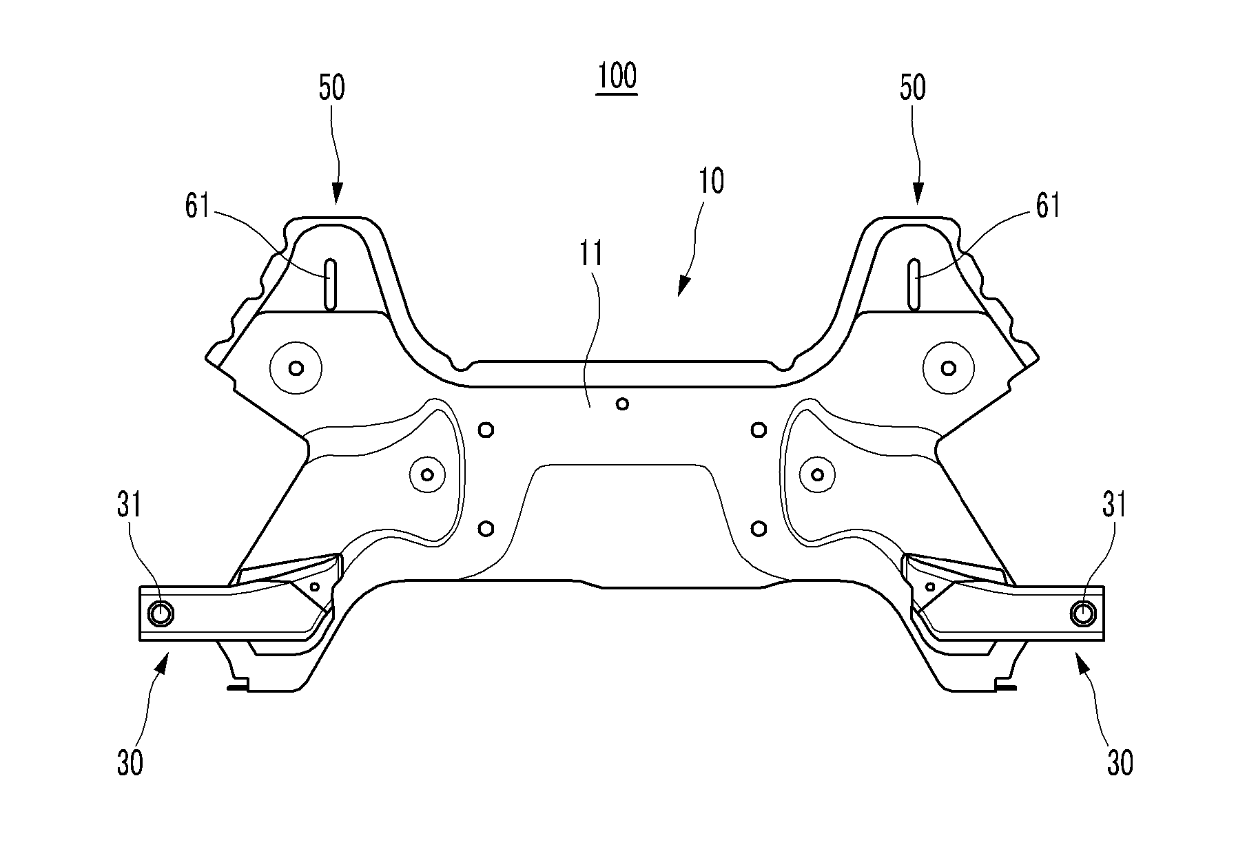
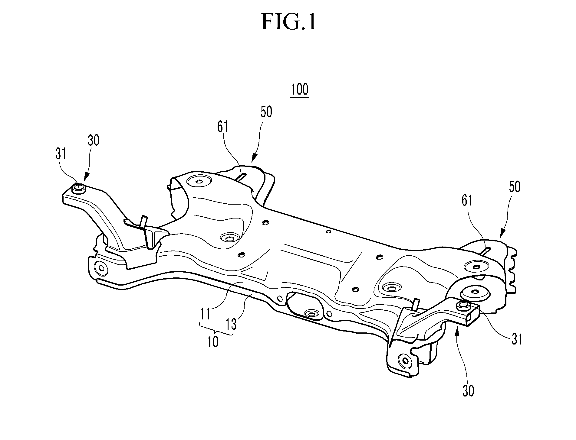
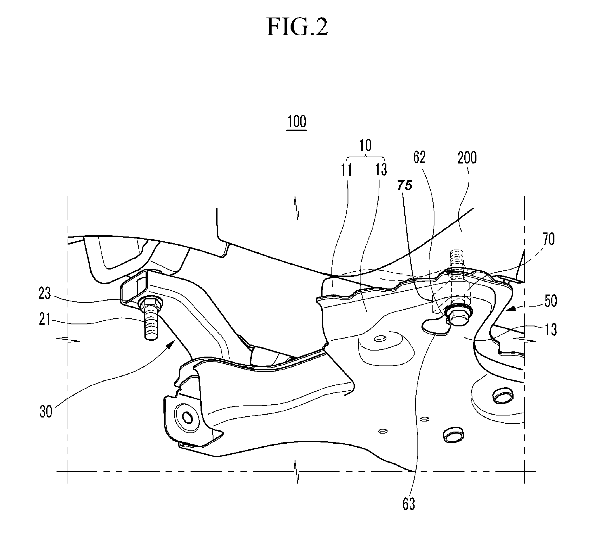
[0031]FIG. 1 is a perspective view of a sub-frame mount for a suspension according to various embodiments of the present invention; FIG. 2 is a perspective view showing a mounting structure of a sub-frame mount for a suspension according to various embodiments of the present invention; and FIG. 3 is a partial cross-sectional view of F...


PUM


Abstract

A sub-frame mount for a suspension may include a frame structure having an upper plate and a lower plate, a front mounting portion provided at a front portion of the frame structure, and connected to a vehicle body through a first mount bolt, and a rear mounting portion provided at a rear portion of the frame structure, and connected to the vehicle body through a second mount bolt, wherein the respective rear mounting portion includes, a first hole formed at the upper plate, a second hole corresponding to the first hole and formed at the lower plate, width of the second hole corresponding approximately to the width of the body of the second mount bolt, and a third hole connected to the second hole so that a head of the second mount bolt can pass through the third hole.

Description

CROSS-REFERENCE TO RELATED APPLICATION[0001]The present application claims priority to Korean Patent Application Number 10-2008-0104901 filed on Oct. 24, 2008, the entire contents of which application is incorporated herein for all purposes by this reference.BACKGROUND OF THE INVENTION[0002]1. Field of the Invention[0003]The present invention relates to a sub-frame mount for a suspension. More particularly, the present invention relates to a sub-frame mount structure to a vehicle body.[0004]2. Description of the Related Art[0005]Generally, a suspension of a vehicle connects an axle to a vehicle body, prevents damage of the vehicle body and freight, and improves ride comfort as a consequence of controlling vibration, impact, and load transmitted from a road to the axle during driving not to be directly transmitted to the vehicle body.[0006]Particularly, MacPherson-type suspensions applied mainly to small vehicles have a sub-frame provided with an upper plate and a lower plate welded ...

Claims


Application Information

Patent Timeline
Patent Type & Authority Patents(United States)
IPC IPC(8): B62D21/11
CPCB62D21/11B62D21/155B62D27/065B62D21/00B62D21/02
Inventor KANG, HEE GON
Owner HYUNDAI MOTOR CO LTD
Learn More