Video signal processing method, video signal processing apparatus, and display apparatus

a video signal and processing method technology, applied in the field of video signal processing methods, video signal processing apparatuses, display apparatuses, can solve problems such as insufficient restoration of video correction data and defects in display images

Inactive Publication Date: 2012-08-21
SHARP KK
View PDF11 Cites 0 Cited by
  • Summary
  • Abstract
  • Description
  • Claims
  • Application Information

AI Technical Summary

Problems solved by technology

However, the method in Japanese Unexamined Patent Publication above has a problem of the insufficient restoration of the video correction data in the LUT 81.
Accordingly, there has been a problem that the time lag in the updates of the video correction data causes defects in display images.

Method used


Image

  • Video signal processing method, video signal processing apparatus, and display apparatus
  • Video signal processing method, video signal processing apparatus, and display apparatus
  • Video signal processing method, video signal processing apparatus, and display apparatus

Examples


referential example

[0104]A Referential Example according to the embodiment above in FIG. 1(a) is briefly described below with reference to FIG. 8.

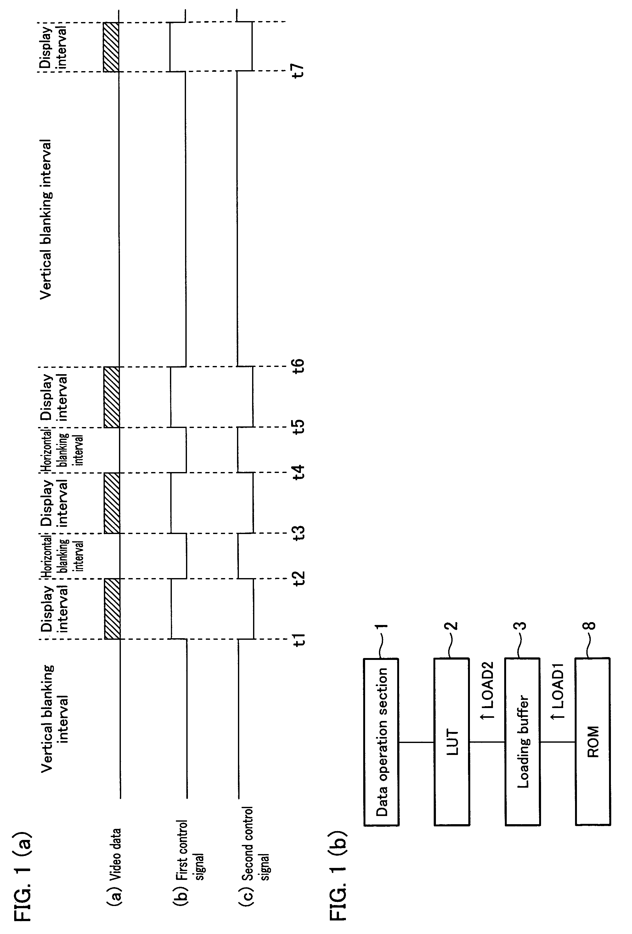
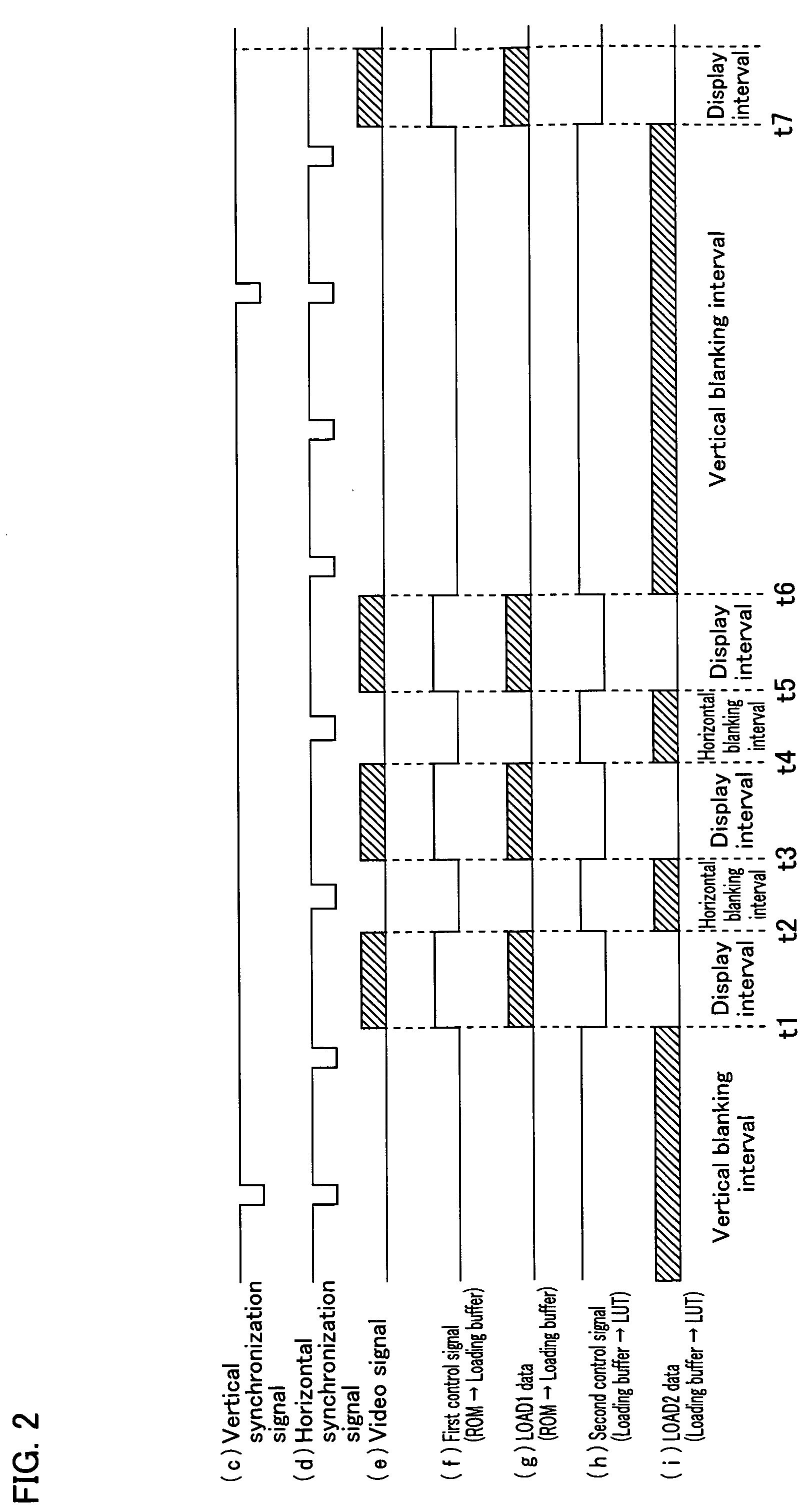
[0105]In FIG. 8, time t31-t32, t33-t34, and t35-36 are the display intervals. Time t32-t33 and t34-t35 are the horizontal blanking intervals. Time t36-t37 is a vertical blanking interval.

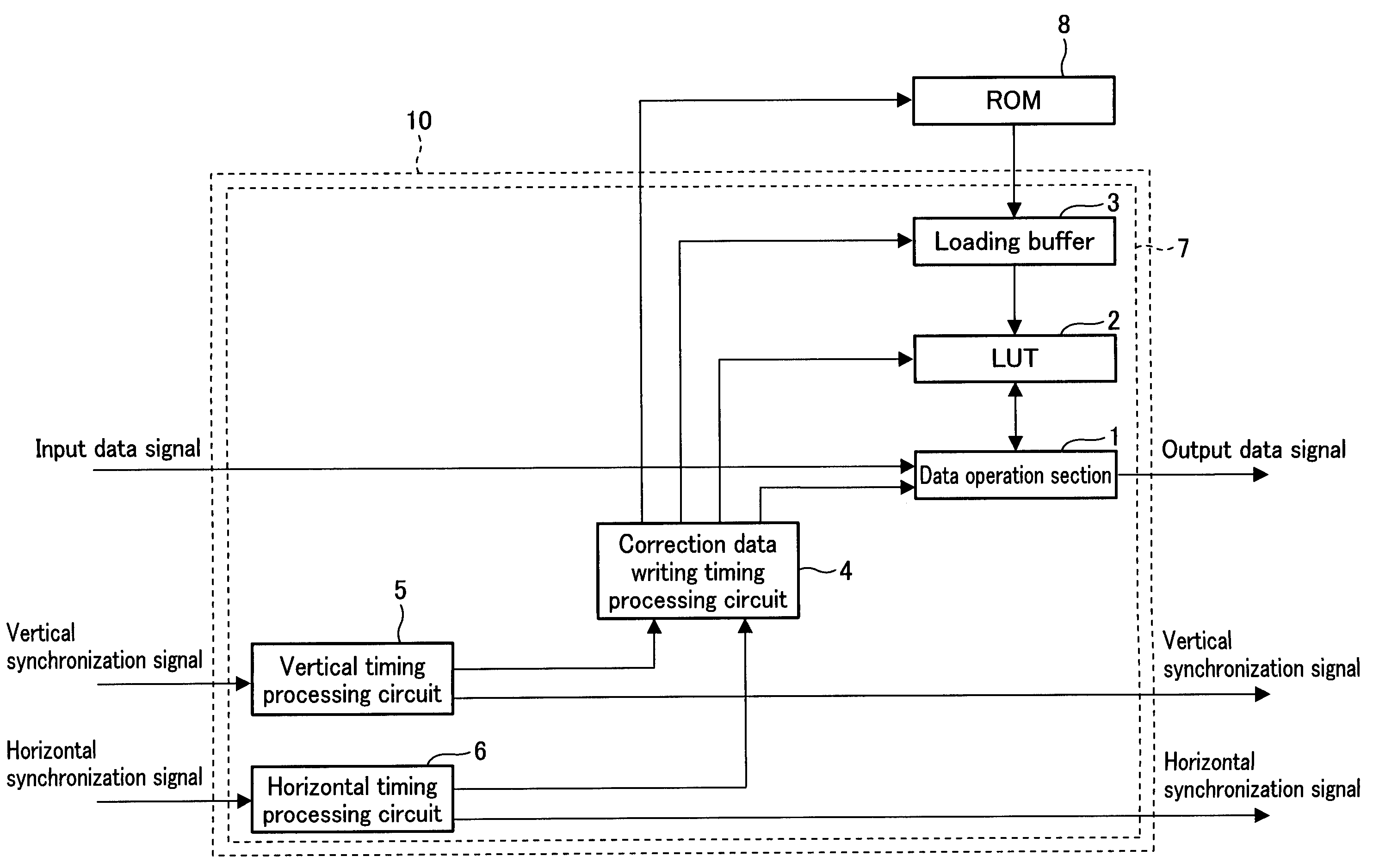
[0106]The waveform (s) represents the display intervals and the blanking intervals (the horizontal blanking intervals and the vertical blanking intervals). The waveform (t) represents the data transfer from a ROM to a buffer. The waveform (u) represents the data transfer from the buffer to a LUT.

[0107]As the waveform (t) indicates, the fourth control signal between the ROM and the buffer is at ‘H’ level during the display intervals and the horizontal blanking intervals while the control signal is at ‘L’ level during the vertical blanking intervals. As the waveform (u) indicates, the fifth control signal between the buffer and the LUT is at ‘L’ level during the display interv...


PUM


Abstract

In one embodiment of the present invention, a video signal processing method is disclosed wherein video correction data is read from a ROM and written into an LUT, and the video correction data written in the LUT is used to perform data correction of an externally inputted video signal. The video correction data written in the LUT is updated during the horizontal blanking interval of the video signal.

Description

TECHNICAL FIELD[0001]The present invention relates to a video signal processing method for video correction data stored in a lookup table, a video signal processing apparatus, and display apparatus.BACKGROUND ART[0002]Liquid crystal display apparatuses utilize video data to display images on a liquid crystal display section. The video data is corrected through data correction such as gamma correction on the control circuit of the liquid crystal display apparatus. A lookup table (LUT) is generally utilized for the data correction. In many cases, LUT is a RAM, which is rewritable, in order that parameters in the LUT may be changed according to different data correction. In this arrangement, video correction data stored in an external ROM in advance is transferred to the LUT before display.[0003]However, the liquid crystal display apparatuses of this arrangement would suffer from destruction of data in the LUT due to noise due to static electricity, etc. during display. Destroyed data ...

Claims


Application Information

Patent Timeline
Patent Type & Authority Patents(United States)
IPC IPC(8): G09G3/36
CPCH04N5/202H04N9/646H04N9/69
Inventor TAKEUCHI, MASAKAZUIWAMOTO, AKIHISAMORII, HIDEKIMIZUNAGA, TAKAYUKI
Owner SHARP KK
Why Eureka
Try Eureka