Fixing mechanism for storage device

a technology for fixing mechanisms and storage devices, which is applied in the direction of lighting support devices, electric apparatus casings/cabinets/drawers, instruments, etc., can solve the problems of troublesome disassembly of storage devices and risk of damaging other working elements of electronic devices

Inactive Publication Date: 2012-08-21
HONG FU JIN PRECISION IND (SHENZHEN) CO LTD +1
View PDF23 Cites 9 Cited by
  • Summary
  • Abstract
  • Description
  • Claims
  • Application Information

AI Technical Summary

Benefits of technology

[0005]A typical fixing mechanism is used to mount a storage device to an electronic device. The electronic device, such as a host computer, can include a case having a base and a sidewall. The fixing mechanism includes a storage device holder, a fixing bracket, and a plurality of screws. The bracket is perpendicularly fixed to the base of the casing, and is separate from the sidewall. The storage device holder includes a mounting protrusion extending from a side surface thereof. The storage device holder is disposed on the base and the mounting protrusion is fixed to the bracket by the screws. The storage device is fixed in the storage device holder. However, a developing trend to miniaturize the electronic device creates insufficient space to disassemble the storage device, rendering disassembly of the storage device troublesome, along with the risk of damaging other working elements of the electronic device during such process.

Problems solved by technology

However, a developing trend to miniaturize the electronic device creates insufficient space to disassemble the storage device, rendering disassembly of the storage device troublesome, along with the risk of damaging other working elements of the electronic device during such process.

Method used


Image

  • Fixing mechanism for storage device
  • Fixing mechanism for storage device
  • Fixing mechanism for storage device

Examples


Embodiment Construction

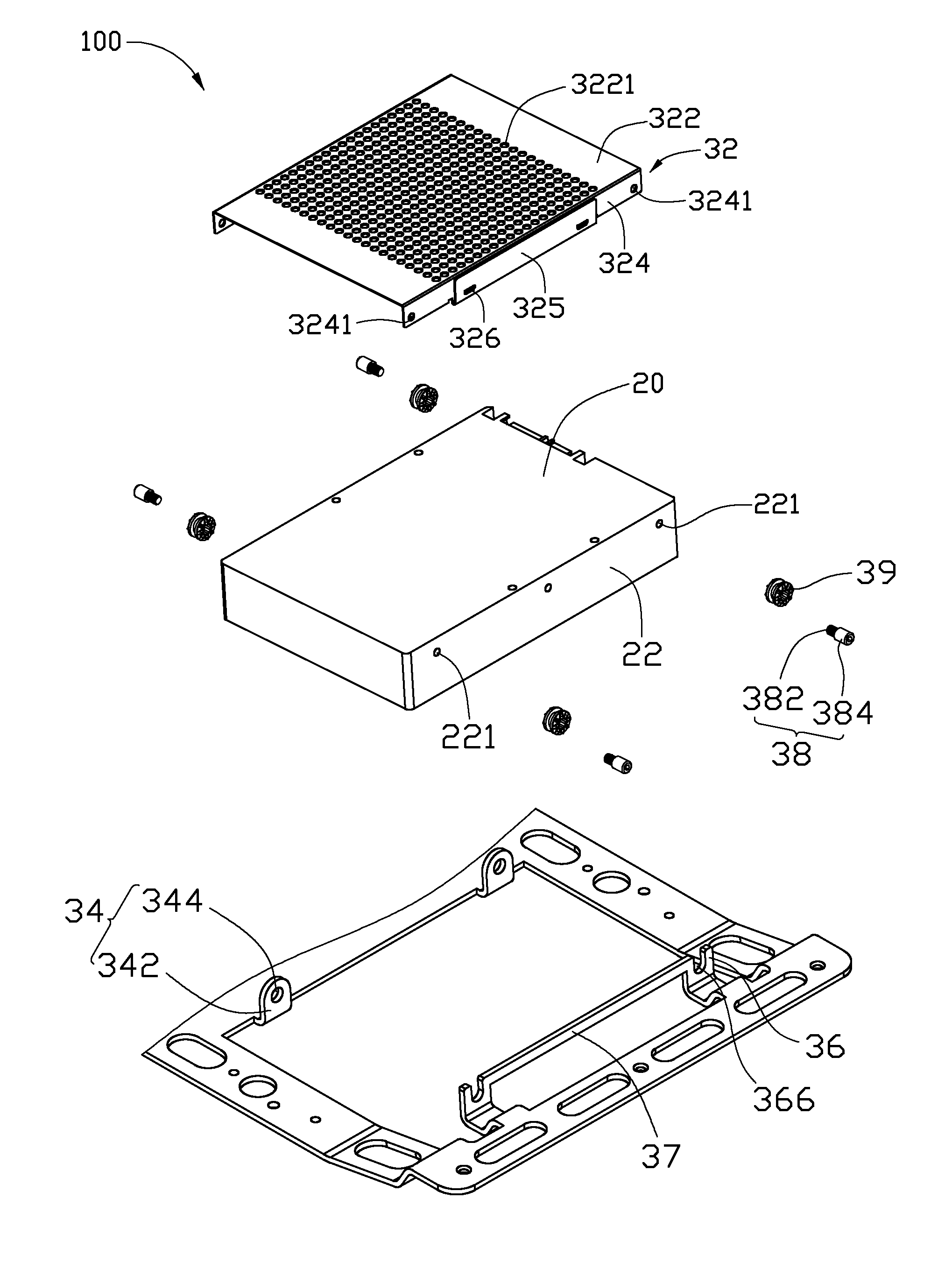
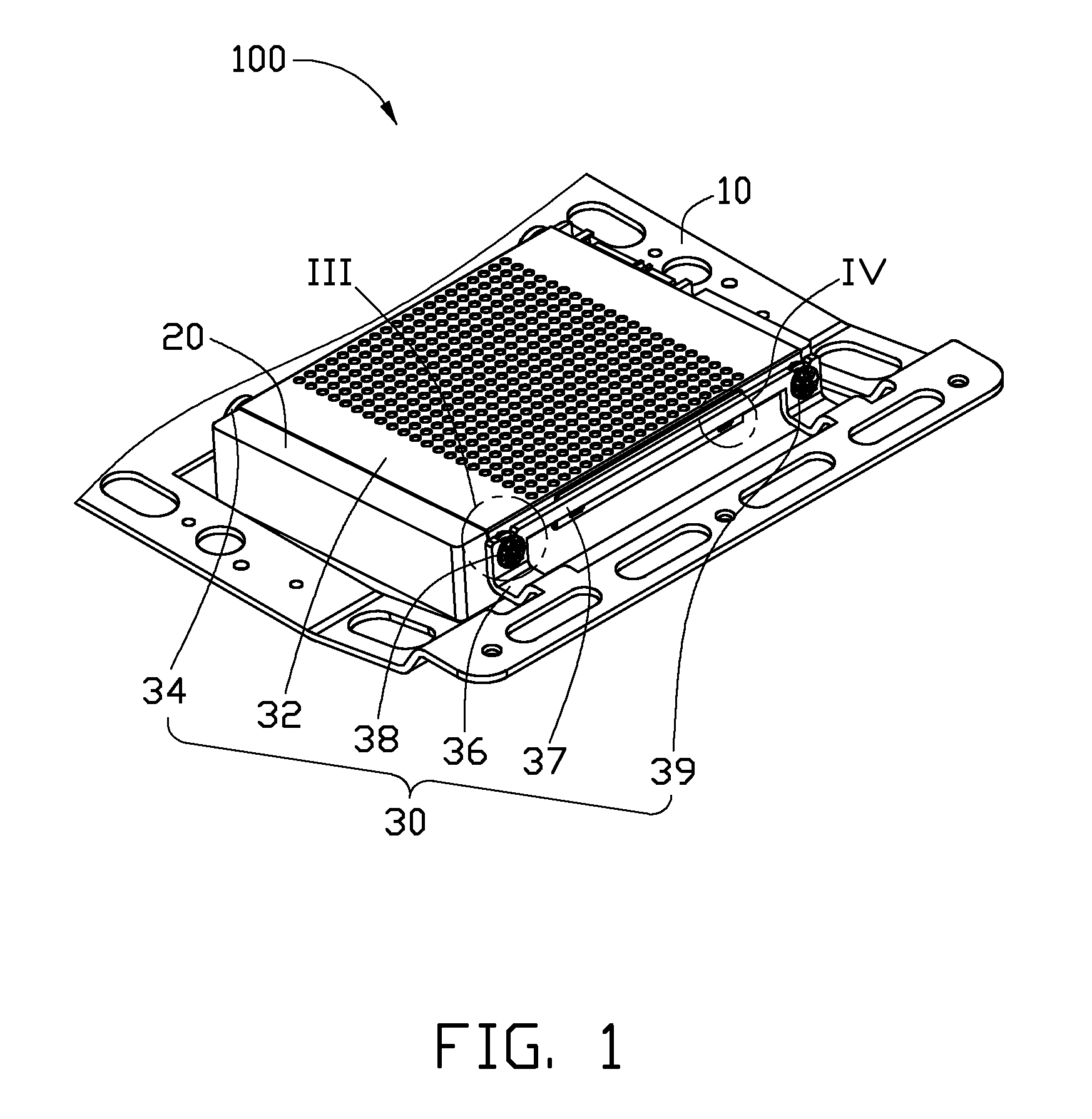
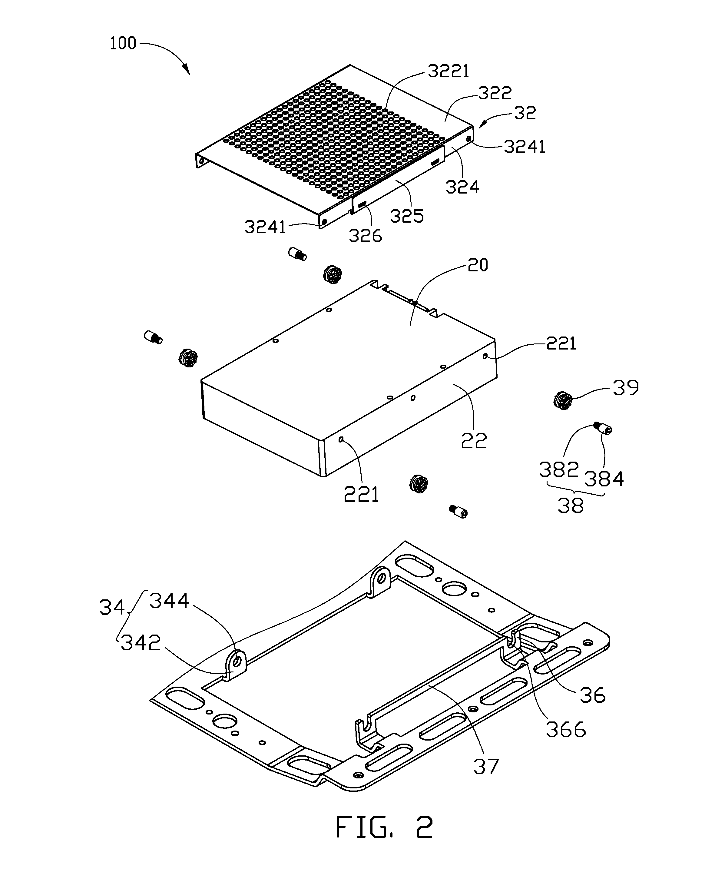
[0013]Referring to FIGS. 1 and 2, a first embodiment of an electronic device 100 includes a bracket 10, a storage device 20, and a fixing mechanism 30 fixing the storage device 20 to the bracket 10. In the illustrated embodiment, the electronic device 100 is a host computer, but can be any device employing a storage device, such as a television set or a handheld game console.

[0014]In the illustrated embodiment, the storage device 20 is a hard-disk drive, substantially cubic, and includes two positioning sides 22 opposite to each other. Each of the positioning sides 22 defines a pair of fixing holes 221 opposite to each other.

[0015]The fixing mechanism 30 includes a limiting member 32, two first supporting members 34, two second supporting members 36, a latching member 37, and two pairs of fixing members 38. The two first supporting members 34 extend out from the bracket 10 and are spaced from each other. The two second supporting members 36 extend out from the bracket 10, and corres...


PUM


Abstract

A fixing mechanism includes a plurality of fixing members, a limiting member, two first supporting members extending from the bracket, two second supporting members formed in the bracket and opposite to the first supporting members, and a latching member adjacent to the second supporting members. The limiting member includes a resilient sheet and a latching portion extending from the resilient sheet. The limiting member is fixed to the storage device with the fixing members at opposite sides of the storage device. The fixing members of one side of the storage device engage with the first supporting member. The fixing members of the other side of the storage device engage with the second supporting member. The latching member is latched with the latching portion of the limiting member, such that the storage device is mounted between the first and second supporting members.

Description

BACKGROUND[0001]1. Technical Field[0002]The present disclosure relates to fixing mechanisms, and particularly, to a fixing mechanism for a storage device.[0003]2. Description of the Related Art[0004]Electronic devices, such as desktop computers and servers often include storage devices, such as hard disk drives, compact disk read-only memory drives, digital video disc drives, floppy disk drives, and so on. These electronic devices are typically incorporated to increase the functionality of the electronic device as desired.[0005]A typical fixing mechanism is used to mount a storage device to an electronic device. The electronic device, such as a host computer, can include a case having a base and a sidewall. The fixing mechanism includes a storage device holder, a fixing bracket, and a plurality of screws. The bracket is perpendicularly fixed to the base of the casing, and is separate from the sidewall. The storage device holder includes a mounting protrusion extending from a side su...

Claims


Application Information

Patent Timeline
Patent Type & Authority Patents(United States)
IPC IPC(8): G06F1/16H05K7/00H05K5/00
CPCG11B33/124
Inventor DAI, BIN
Owner HONG FU JIN PRECISION IND (SHENZHEN) CO LTD
Why Eureka
Try Eureka