

Power delivery apparatus
- Summary
- Abstract
- Description
- Claims
- Application Information
AI Technical Summary
Benefits of technology
Problems solved by technology
Method used
Image

Examples
first embodiment
Modification of First Embodiment
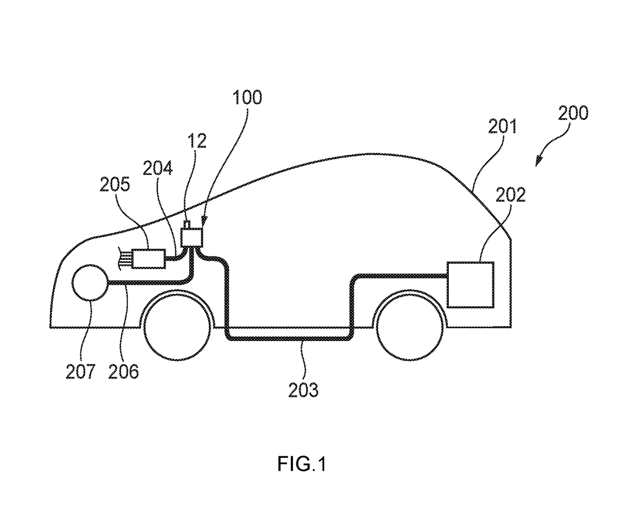
[0067]As illustrated in FIG. 5, an output terminal 26 (the output terminal 14 in FIG. 4) connected to the starter motor 207 may be provided not in the upstream delivering portion 10 but in the downstream delivering portion 20. The output terminal 26 (direct output terminal) is connected to an upstream circuit position from the fuse portions 22a to 22e so that electric power can be outputted directly not through the fuse portions 22a to 22e of the downstream delivering portion 20.
[0068]According to this configuration, electric power from the battery 202 can be supplied to the starter motor 207 from the downstream delivering portion 20 directly not through the fuse portions 22a to 22e. Accordingly, electric power can be supplied through the downstream delivering portion 20 to an electric device such as the starter motor 207 for which the fuse function in the power delivery apparatus 100 is dispensable. Thus, change of design of such an electric device c...
second embodiment
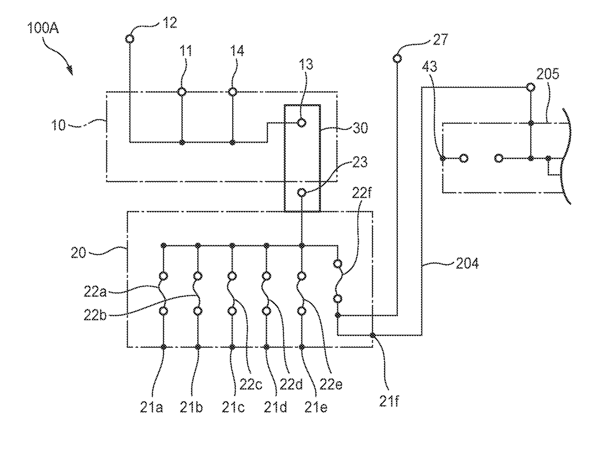
[0069]FIGS. 6A and 6B illustrates a downstream delivering portion 20 of a power delivery apparatus (hereinafter referred to as “power delivery apparatus 100A”) according to a second embodiment of the invention. The power delivery apparatus 100A according to the second embodiment is different from the power delivery apparatus 100 according to the first embodiment at the point that the downstream delivering portion 20 includes a specific fuse portion 22f having capacity high enough to serve as the main fuse 42 in the relay box 205.
[0070]In particular, as illustrated in FIGS. 6A and 6B, the downstream delivering portion 20 is provided with an output terminal 21f, an output terminal 27, and the specific fuse portion 22f. The power path 204 connected to the relay box 205 of the vehicle 200 can be connected to the output terminal 21f. A power path connected to an alternator (not illustrated) is connected to the output terminal 27. The specific fuse portion 22f can serve as a main fuse (ma...
PUM
 Abstract
Description
Claims
Application Information