Imaging apparatus

a technology of imaging apparatus and lens barrel, which is applied in the field of lenses, can solve problems such as sound effects, and achieve the effect of lowering the sound of collision

Inactive Publication Date: 2012-08-28
RICOH KK
View PDF17 Cites 6 Cited by
  • Summary
  • Abstract
  • Description
  • Claims
  • Application Information

AI Technical Summary

Benefits of technology

[0010]The present invention has been made with the foregoing circumstances taken into consideration. An object of the present invention is to provide a lens barrel capable of lowering a collision sound occurring when a retractable lens is positioned on a photographic optical axis.

Problems solved by technology

Thus, there is a drawback that a collision sound may occur due to the abutment.

Method used


Image

  • Imaging apparatus
  • Imaging apparatus
  • Imaging apparatus

Examples


embodiment 1

(Embodiment 1)

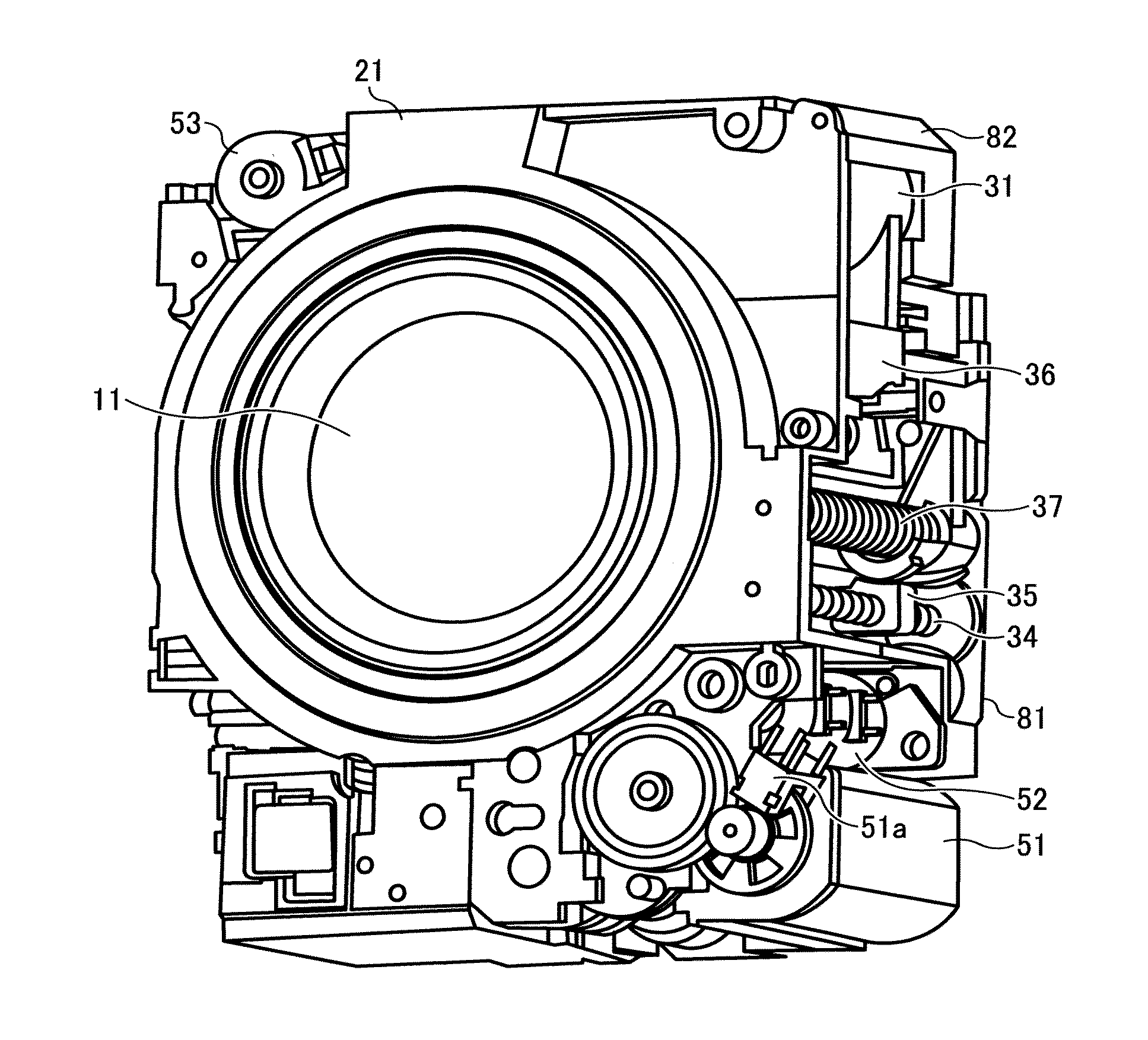
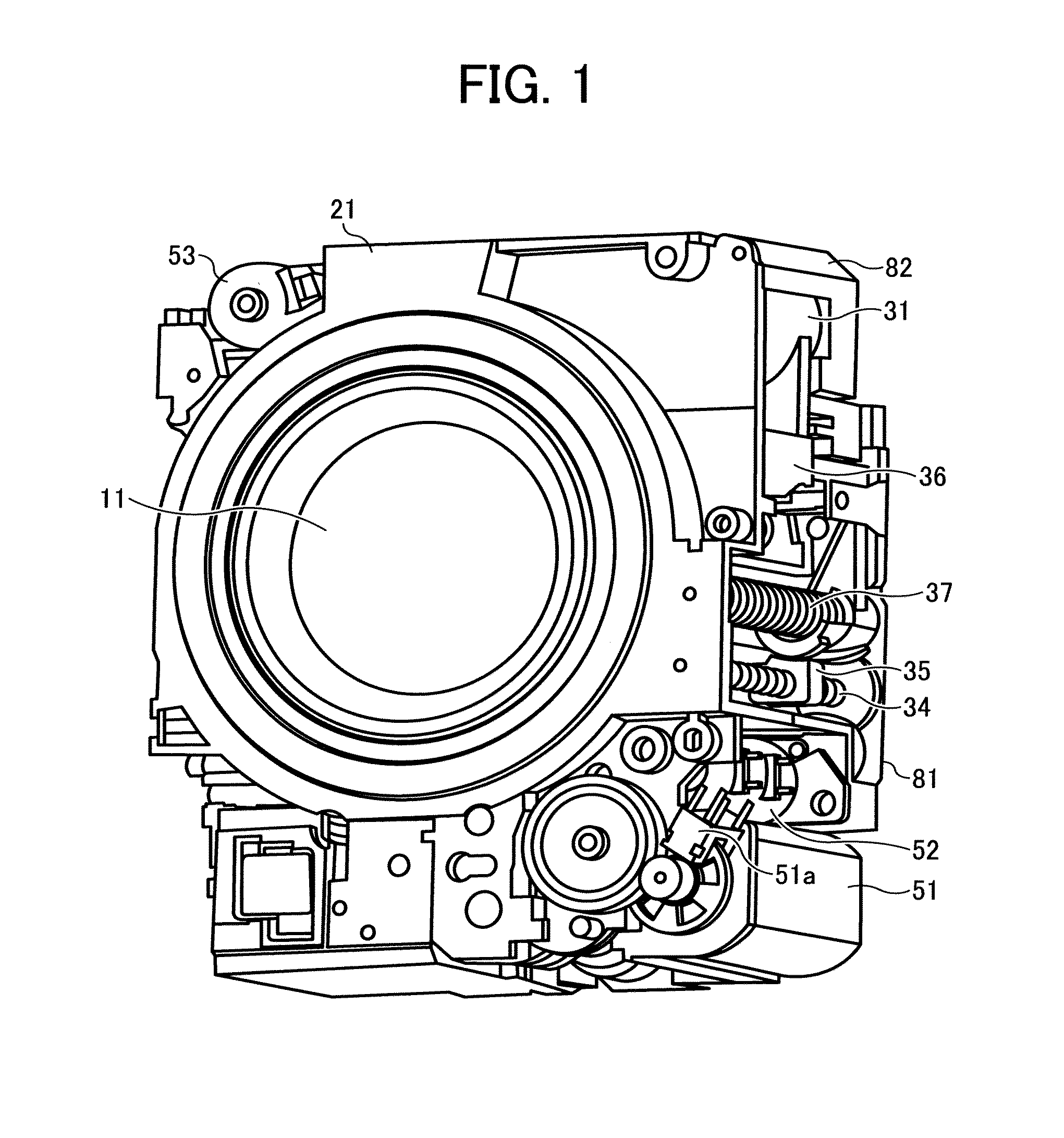
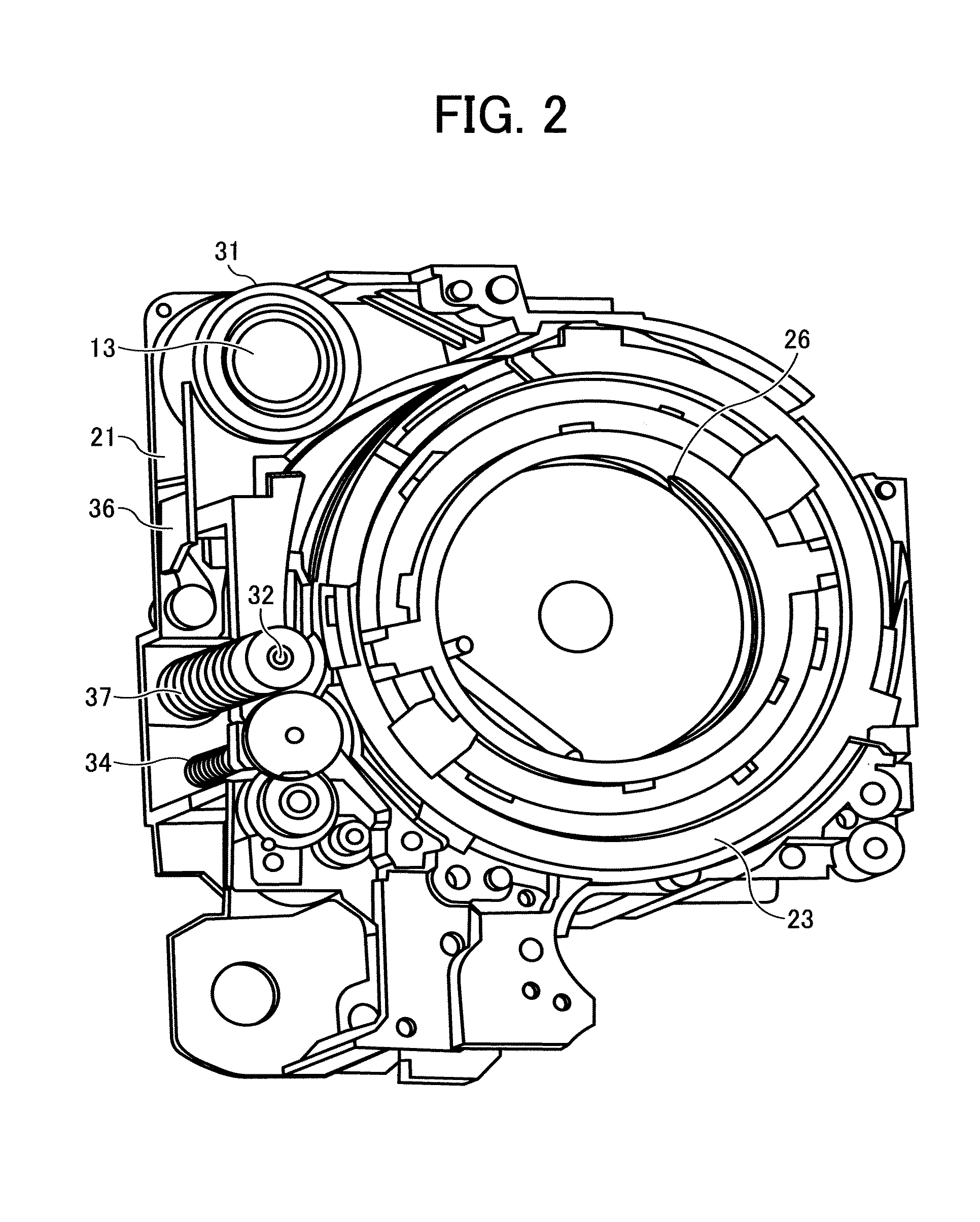
[0060]Descriptions will be provided for a lens barrel 10 of Embodiment 1 as an embodiment of a lens barrel of the present invention by use of FIGS. 1 to 21. It should be noted that FIGS. 1 to 16B and 20 show configurations and various operating states of main parts of an optical system apparatus including the lens barrel 10 of the present invention.

[0061]In FIGS. 1 to 16B and 20, the optical system apparatus including the lens barrel 10 according to an embodiment of the present invention including a plurality of lens groups each having at least one lens, a plurality of lens retaining frames each configured to retain corresponding one of the plurality of lens groups, a movable cylinder configured to accommodate the plurality of lens retaining frames therein, and a lens retaining frame driving device configured to drive the plurality of lens retaining frames through the movable cylinder. The plurality of lens groups is moved between a collapsed state where at least one p...

embodiment 2

(Embodiment 2)

[0151]Next, descriptions will be provided for a lens barrel 10A of Embodiment 2 of the present invention. Embodiment 2 is an embodiment in which a preliminary abutment portion 91A of a third lens retaining frame 31A is different in the configuration. The basic configuration of the lens barrel 10A of Embodiment 2 is the same as that of the lens barrel 10 of Embodiment 1 which has been described above. For this reason, the same configuration parts will be denoted by the same reference signs, and detailed descriptions for such configuration parts will be omitted. FIG. 34 is a schematic cross-sectional view for explaining the configuration of the preliminary abutment portion 91A of the third lens retaining frame 31A in the lens barrel 10A of Embodiment 2, and shows the configuration thereof in a manner similar to that of FIG. 28.

[0152]In the lens barrel 10A of Embodiment 2, as shown in FIG. 34, a rubber sheet 91Ab is provided to the preliminary abutment portion 91A of the ...

embodiment 3

(Embodiment 3)

[0160]Next, descriptions will be provided for a lens barrel 10B of Embodiment 3 of the present invention. Embodiment 3 is an embodiment in which a preliminary reception portion 92B of the barrel base 82 is different in the configuration. The basic configuration of the lens barrel 10B of Embodiment 3 is the same as that of the lens barrel 10 of Embodiment 1 which has been described above. For this reason, the same configuration parts will be denoted by the same reference signs, and detailed descriptions for such configuration parts will be omitted. FIG. 35 is a schematic cross-sectional view for explaining the configuration of the preliminary reception portion 92B of the barrel base 82 in the lens barrel 10B of Embodiment 3, and shows the configuration thereof in a manner similar to that of FIG. 28.

[0161]In the lens barrel 10B of Embodiment 3, as shown in FIG. 35, a rubber sheet 92Bb is provided to an inclined receiving surface 92Ba of the preliminary reception portion ...


PUM


Abstract

A lens barrel includes a plurality of lenses moved between a collapsed state where at least one lens is collapsed and a photographic state where at least one lens is disposed at an object side and all lenses are on a photographic axis, a plurality of lens retaining frames each configured to retain the plurality of lenses, a movable cylinder, a positioning member provided inside the movable cylinder, the retractable lens retaining frame retaining a retractable lens to be positioned to a photographic axis position by allowing the retractable lens retaining frame to abut on the positioning member in the photographic state and to be retracted out of the photographic axis in the collapsed state, a preliminary reception portion provided inside the movable cylinder and located on a path along which the retractable lens retaining frame moves from the collapsed state to the photographic state.

Description

CROSS REFERENCE TO RELATED APPLICATIONS[0001]The present application is based on and claims priority from Japanese Application Number 2010-027648, filed on Feb. 10, 2010, the disclosure of which is hereby incorporated by reference herein in its entirety.BACKGROUND OF THE INVENTION[0002]1. Field of the Invention[0003]The present invention relates to a lens barrel which retracts lens groups in one mode, and which extends the lens groups to their predetermined positions in another mode for use. Particularly, the present invention relates to a lens barrel, a camera, a portable information terminal device and an image input apparatus which are suitable for a zoom lens capable of changing its focal length by moving multiple lens groups relative to one another.[0004]2. Description of the Related Art[0005]Photographic apparatuses, such as digital cameras, have undergone evolutions such as enhancement of the performance of photographic lenses including a zoom lens, and reduction in size in r...

Claims


Application Information

Patent Timeline
Patent Type & Authority Patents(United States)
IPC IPC(8): G03B5/02
CPCG02B7/102G03B17/04
Inventor KOYAMA, TERUNORI
Owner RICOH KK
Why Eureka
Try Eureka