Bracket for mounting electrical junction boxes

a technology for mounting brackets and electrical junction boxes, which is applied in the direction of washstands, coupling device connections, lighting support devices, etc., can solve the problems of expensive and time-consuming process of bending electrical conduits, and prove difficul

Inactive Publication Date: 2012-08-28
HOPKINS LARRY D
View PDF28 Cites 29 Cited by
  • Summary
  • Abstract
  • Description
  • Claims
  • Application Information

AI Technical Summary

Problems solved by technology

This can prove difficult if there is little space between the top plate and the roofing of the structure.
Another common drawback with typical electrical conduits is that they must be shaped in order to interface with the electrical junction boxes.
Typical electrical conduits can be difficult to shape, thus bending the electrical conduits is a costly and time-intensive process.

Method used


Image

  • Bracket for mounting electrical junction boxes
  • Bracket for mounting electrical junction boxes
  • Bracket for mounting electrical junction boxes

Examples


Embodiment Construction

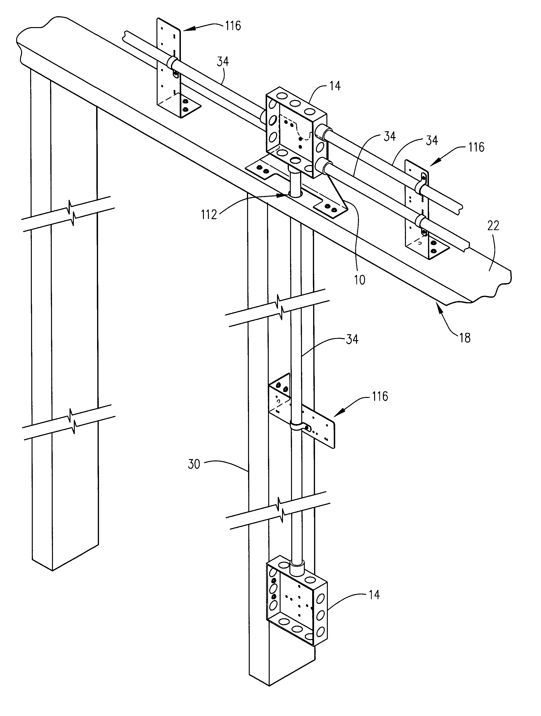
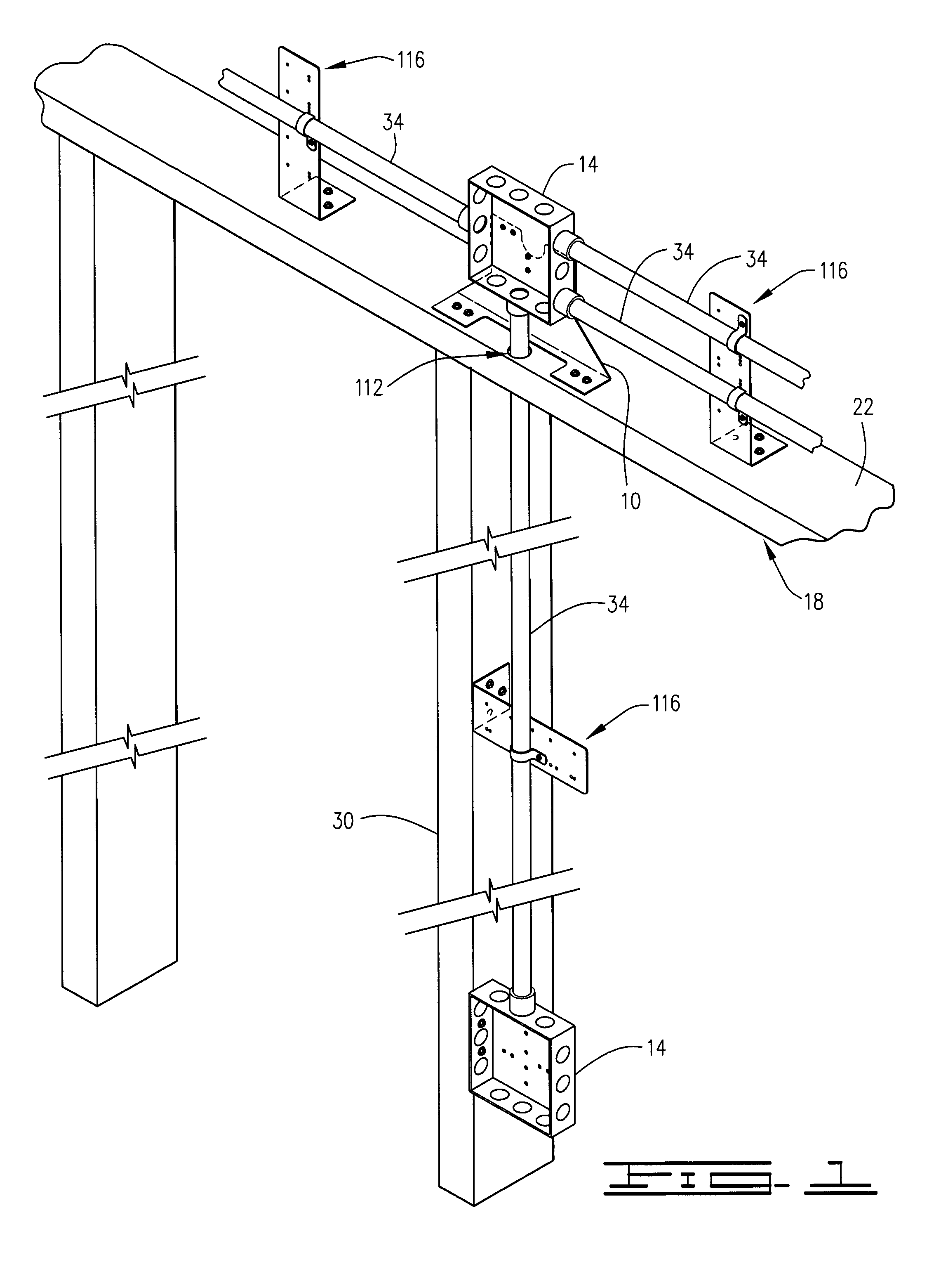
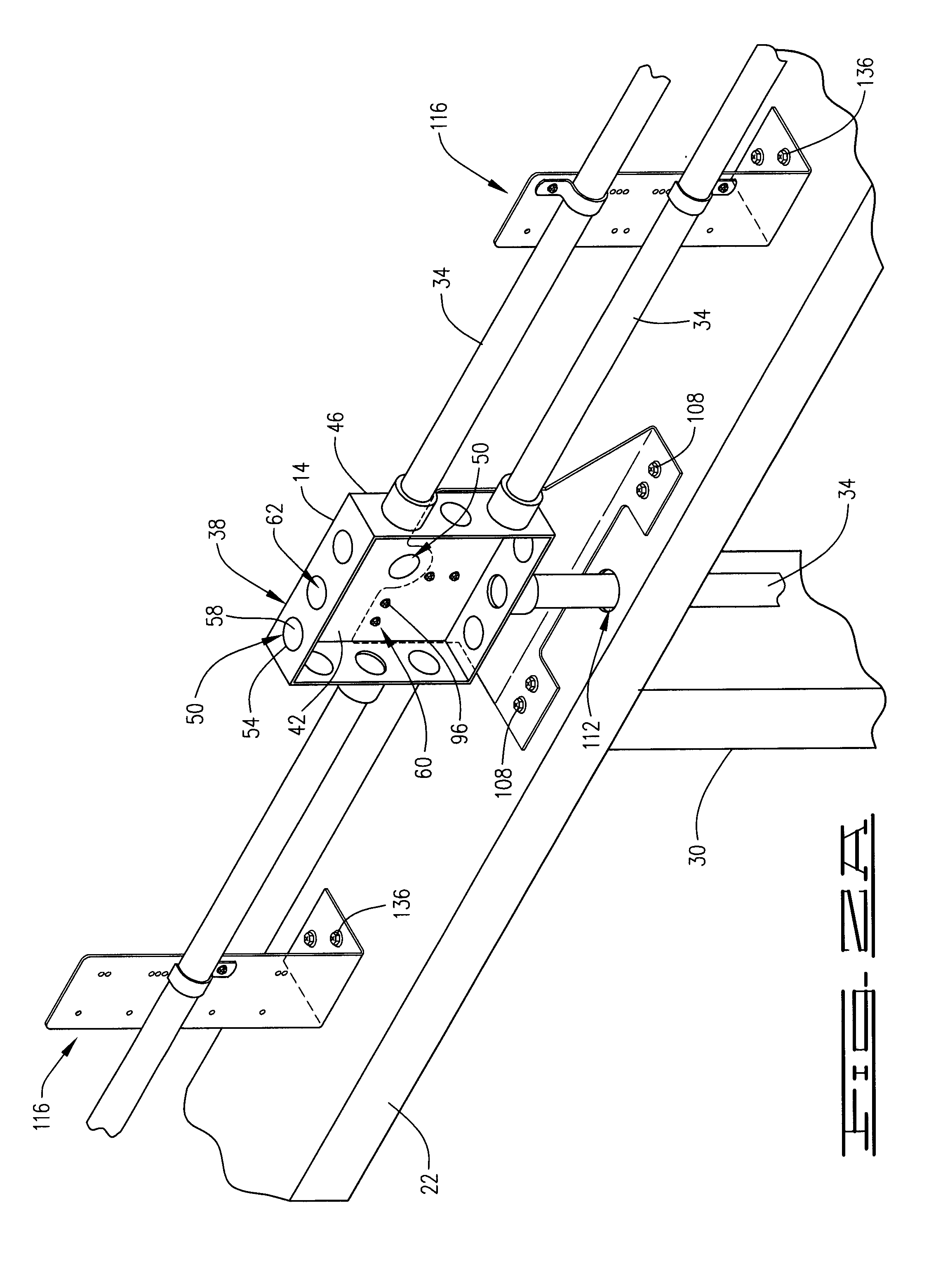
[0023]Referring now to the drawings and more particularly, to FIGS. 1-2B collectively, shown therein is a mounting bracket 10 for use in mounting an electrical junction box 14 in a vertical orientation along a frame wall 18. Furthermore, the mounting bracket 10 allows the electrical junction box 14 to be spaced away from the frame wall 18 at a distance. In general, the frame wall 18 includes the top plate 22, bottom plate (not shown) and wall studs 30. The electrical junction boxes 14 are connected to the frame wall 18 via the mounting bracket 10 and interface with one or more electrical conduits 34 carrying electrical conductor lines. The electrical junction boxes 14 function as transition points which allow the electrical conduits 34 to transition from a vertical orientation to a horizontal orientation and vice versa. More particularly, the electrical junction box 14 disposed along the top plate 22 allows electrical conduits 34 running substantially parallel to the top plate 22 to...


PUM


Abstract

A mounting bracket for spacing an electrical junction box at a distance away from a portion of a frame wall, the frame wall having a top plate, a bottom plate and one or more wall studs extending the top plate and the bottom plate, the electrical junction box having a back plate and one or more sidewalls extending from the back plate, the one or more sidewalls adapted to receive one or more electrical conduits, the mounting bracket having a back plate and an securement plate.

Description

CROSS REFERENCE TO RELATED APPLICATIONS[0001]This application claims benefit of U.S. Provisional Application No. 61 / 177,529, filed May 12, 2009, which is hereby incorporated herein by reference in its entirety.BACKGROUND OF THE INVENTION[0002]1. Field of the Invention[0003]This invention relates to a mounting bracket, and more particularly, but not by way of limitation, to a mounting bracket for spacing electrical junction boxes at a distance away from the framing studs of a structure, including top plates and vertical framing studs such that electrical conduits may interface with the electrical junction boxes in such a way that the electrical conduits remain unbent.[0004]2. Brief Description of Related Art[0005]The installation and use of electrical junction boxes is well known in the art, particularly in applications where the electrical junction boxes are used in combination with tubular metallic conduits which function to carry electrical conductor lines. While the installation ...

Claims


Application Information

Patent Timeline
Patent Type & Authority Patents(United States)
IPC IPC(8): H02B1/40
CPCH02G3/126H02G3/32
Inventor HOPKINS, LARRY D.
Owner HOPKINS LARRY D
Why Eureka
Try Eureka