Battery voltage monitoring system for monitoring the battery voltage of a series arrangement of more than two batteries

a battery voltage monitoring and battery technology, applied in the field of battery voltage monitoring system for monitoring the battery voltage of a series arrangement of more than two batteries, can solve the problems of unexpected increase in measurement errors, permanent damage to the battery, etc., and achieve the effect of accurately monitoring the individual battery voltage and increasing the accuracy of voltage measuremen

Active Publication Date: 2012-08-28
VERSUNI HLDG BV
View PDF9 Cites 5 Cited by
  • Summary
  • Abstract
  • Description
  • Claims
  • Application Information

AI Technical Summary

Benefits of technology

[0004]It is an object of the invention to provide an improved battery voltage monitoring system in which the accuracy of the voltage measurement is increased. This invention aims to accurately monitor the individual battery voltage of an arrangement of series connected batteries.
[0006]When the transistor is addressed the voltage across the first resistor becomes substantially equal to the voltage between two nodes in the battery arrangement. This allows directly measuring the voltage difference over an individual battery, thus eliminating sources of error.
[0007]In a preferred embodiment, two or more voltage dividers have a common resistor. The use of a common resistor reduces measurement errors.
[0008]In a preferred embodiment, the diode is comprised in a transistor which matches the transistor in the voltage divider. This reduces errors.

Problems solved by technology

Otherwise this will result in permanent damage to the battery.
Using the known scheme, however, the errors in measurement increase as more and more batteries are used.
This leads to errors.
Such errors may result in unexpected damage to the battery, or, if a safety margin is applied, in switching off of the device at a real voltage of substantially higher than 2.7 Volts or terminating charging of the batteries at a voltage substantially lower than 4.2 V.

Method used


Image

  • Battery voltage monitoring system for monitoring the battery voltage of a series arrangement of more than two batteries
  • Battery voltage monitoring system for monitoring the battery voltage of a series arrangement of more than two batteries
  • Battery voltage monitoring system for monitoring the battery voltage of a series arrangement of more than two batteries

Examples


Embodiment Construction

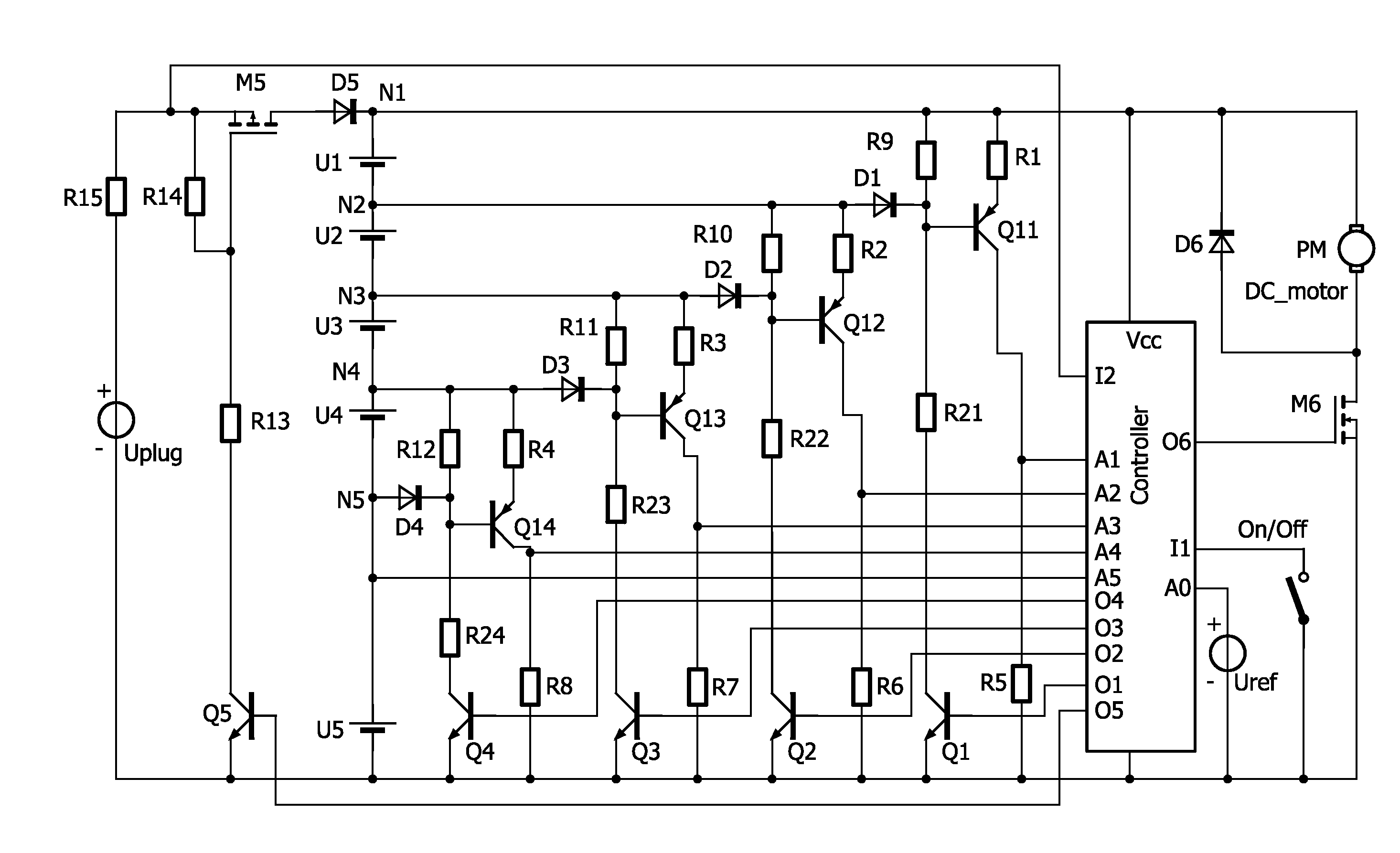
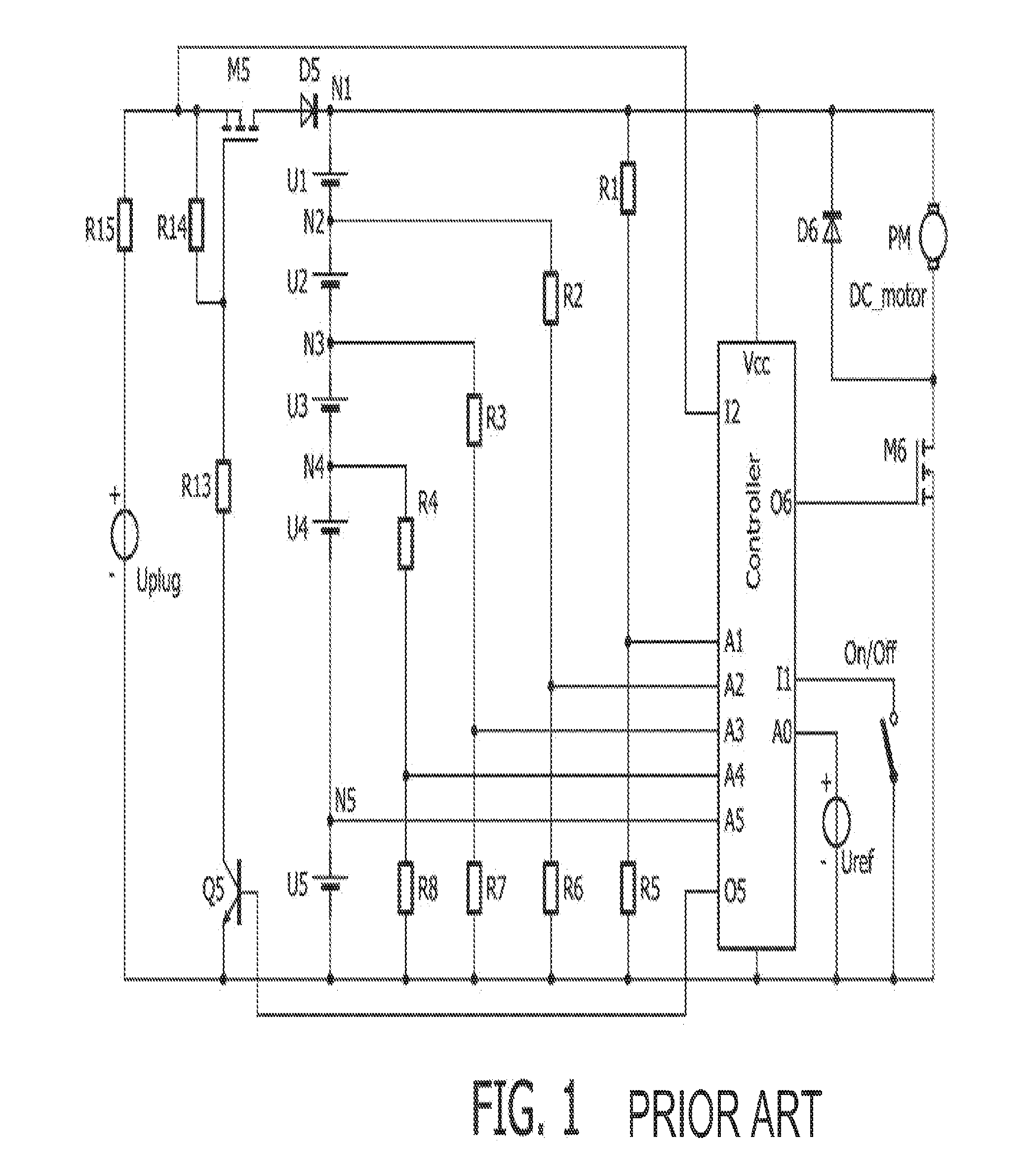
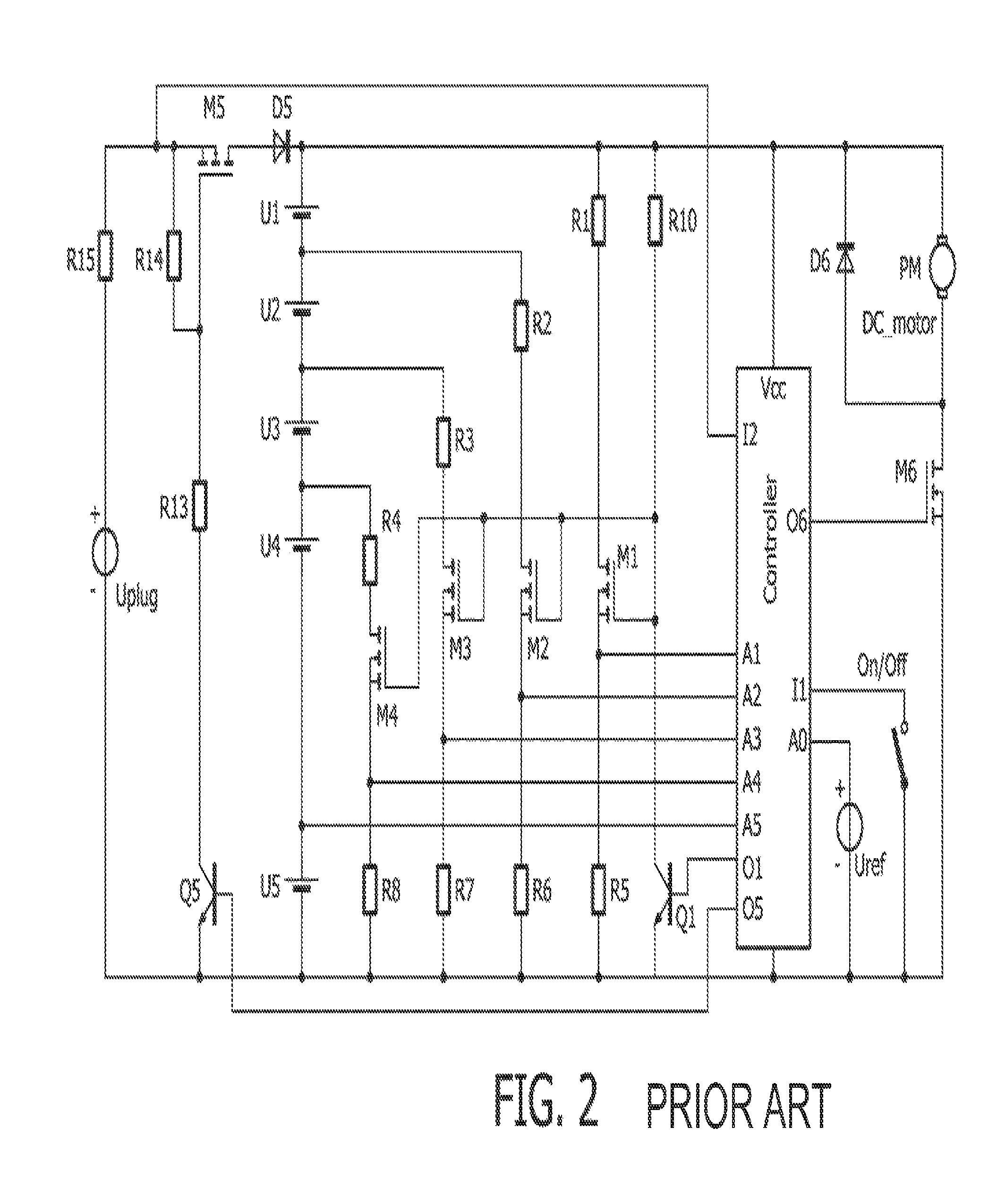
[0022]In FIG. 1 a general Li-ion battery management system is presented. It exists of a low voltage power plug (or “adaptor”), a series connection of Li-ion batteries (in this example five batteries), a controller, an On / Off switch and means to measure voltages. With Mosfet M5 the charging current can be interrupted. With Mosfet M6 the appliances can be switched On and Off when the On / Off switch is controlled.

Charging

[0023]The battery-operated appliance (Hand held vacuum cleaner, power tool etc.) will be charged if the presence is detected of the power plug voltage Uplug, by mean of the controller at input 12. If the batteries have a low charging state, the controller changes output O5 from low to high state. This switches on transistor Q5 and PMosfet M5. Resistor R15 limits the charging current. During charging the voltage of each individual battery will increase. The voltage of each individual battery (U1 to U5) must be monitored. If the battery voltage exceeds the limit of 4.2 Vo...


PUM

PropertyMeasurementUnit
voltageaaaaaaaaaa
battery voltageaaaaaaaaaa
voltageaaaaaaaaaa

Abstract

A battery voltage monitoring system monitors voltage of an arrangement of more than two batteries (U1, U2, U3, U4, U5) in series. The system comprises a voltage divider comprises a first (R1, R2, R3, R4) and second resistive element (R5, R6, R7, R8) arranged parallel to at least a part of the battery arrangement and connected to a reference voltage line and to a node (N1, N2, N3, N4) in the battery arrangement. In between the first (R1, R2, R3, R4) and second resistive element (R5, R6, R7, R8) a transistor (Q11, Q12, Q13, Q14) is arranged. The base of the transistor is, via a diode (D1, D2, D3, D4), connected to a further node (N2, N3, N4, N5) in the series arrangement of batteries, and a switching element (Q1, Q2, Q3, Q4) is provided to address the transistor (Q11, Q12, Q13,Q14).

Description

FIELD OF THE INVENTION[0001]The invention relates to a battery voltage monitoring system for monitoring battery voltage of a battery arrangement of more than two batteries in series, connected at one end to a reference voltage, wherein the monitoring system comprises a voltage divider comprising a first and second resistive element arranged parallel to at least a part of the battery arrangement and connected at one end to the reference voltage and at the other end to a node in the battery arrangement.DESCRIPTION OF PRIOR ART[0002]If an appliance is equipped with for instance Li-ion batteries, a more or less complex battery management system is required. Li-ion batteries and also Li-polymer have to be protected against over voltage (<4.2V) during charging. During use of the appliance the batterie(s) will be discharged. If the battery voltage of any of the batteries in the arrangement passes a certain lower limit, for instance 2.7 Volts, the appliance must be actively switched off ...

Claims


Application Information

Patent Timeline
Patent Type & Authority Patents(United States)
IPC IPC(8): G01N27/416
CPCG01R15/04H01M10/482G01R31/362G01R19/16542G01R31/3648G01R31/3658G01R31/396G01R31/3835Y02E60/10
Inventor HEERINGA, SCHELTEETTES, WILHELMUSBISSCHOP, OEDILIUS JOHANNESVAN DER BURG, JOB VAN DERHOMAN, PASCAL
Owner VERSUNI HLDG BV
Why Eureka
Try Eureka