Position pegs for a three-dimensional reference grid

a three-dimensional reference grid and position peg technology, applied in the field of three-dimensional (3d) authoring application interfaces, can solve the problems of difficult reference visualization, many of the perceptual cues we rely on to understand relative position and distance in the real world are not always easily conveyed in static two-dimensional projections of 3d space, and the technique is often not practical

Active Publication Date: 2012-09-04
AUTODESK INC
View PDF4 Cites 12 Cited by
  • Summary
  • Abstract
  • Description
  • Claims
  • Application Information

AI Technical Summary

Benefits of technology

[0011]One advantage of the disclosed method is that it provides users with continuous orientation, position, and scale reference imagery in 3D application programs.

Problems solved by technology

Reference visualization is significantly more difficult than it may seem, since it spans a huge problem domain with many special cases.
Many of the perceptual cues we rely on to understand relative position and distance in the real world are not always easily conveyed in static two-dimensional projections of 3D space.
Some of the fundamental difficulties in 3D interaction involve being inside or outside of an object, closeness of the viewpoint to an object, egocentric vs. egocentric thinking in terms of determining what the end user is looking at, and parallel vs. perspective viewing projections.
3D application programs such as video games put significant effort into providing realistic texturing, shading, and shadowing to provide users with depth cues, but these techniques are often not practical while the end user is creating a new 3D model using a 3D authoring application program since the scene content is not constrained.
However, this approach has some problems that limit its utility.
The end user may also have difficulty determining whether the viewpoint is above or below the grid and how objects in the scene relate to each other.
However, objects in the scene often fall outside of the fixed-sized grid or completely encompass the grid.
Unfortunately, this workflow forces the end user to work primarily from memory to guide future decisions and actions.

Method used


Image

  • Position pegs for a three-dimensional reference grid
  • Position pegs for a three-dimensional reference grid
  • Position pegs for a three-dimensional reference grid

Examples


Embodiment Construction

[0031]In the following description, numerous specific details are set forth to provide a more thorough understanding of the present invention. However, it will be apparent to one of skill in the art that the present invention may be practiced without one or more of these specific details. In other instances, well-known features have not been described in order to avoid obscuring the present invention.

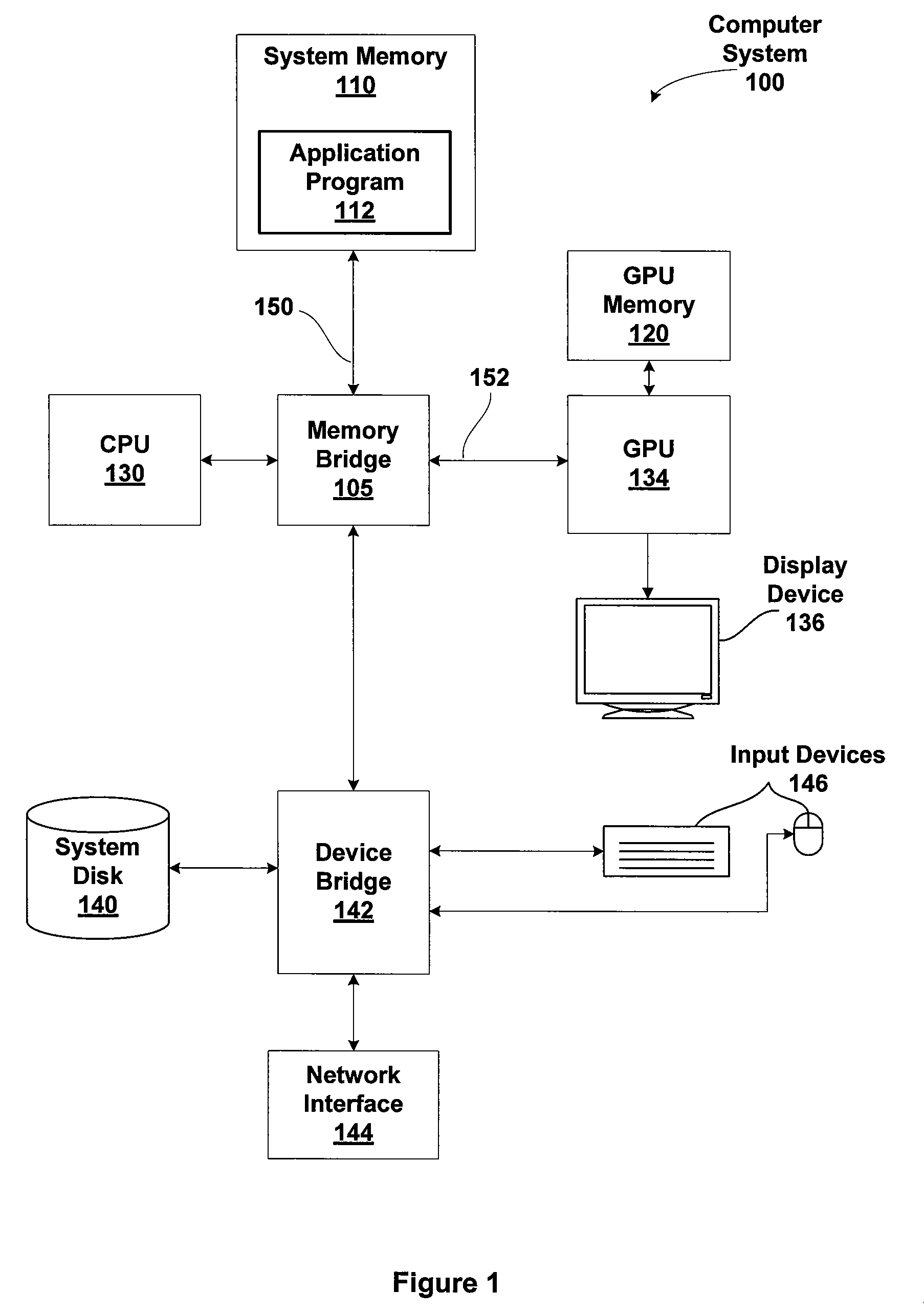
[0032]FIG. 1 illustrates a computer system 100 configured to implement one or more aspects of the present invention. The computer system 100 includes, without limitation, a central processing unit (CPU) 130, a system memory 110, a graphics processing unit (GPU) 134, a GPU memory 120, a memory bridge 105, a display device 136, a system disk 140, a device bridge 142, a network interface 144, a mouse 146, and input devices 146.

[0033]The CPU 130 communicates with the system memory 110 via the memory bridge 105, which may be, e.g., a Northbridge device or subsystem. System memory 110 is conf...


PUM


Abstract

One embodiment of the present invention sets forth a technique for providing position pegs between objects and a three-dimensional reference grid that is displayed in design software application programs. The reference grid appears infinite in space and scale. A position peg that includes a stalk and base is drawn between each object and the reference grid. The stalk indicates the height of the object above or below the reference grid, and the base is positioned on the reference grid. An inside radius of the base indicates the distance between the object and the reference grid. The position pegs are independent of the viewing projection and allow an end user to sense how objects in workspace relate to each other in terms of position and scale. The reference grid and position pegs provide an end user with reference imagery for camera-operation visualization and scene content understanding.

Description

BACKGROUND OF THE INVENTION[0001]1. Field of the Invention[0002]Embodiments of the present invention relate generally to a three-dimensional (3D) authoring application interface and more specifically to position pegs for a 3D reference grid.[0003]2. Description of the Related Art[0004]Conventional reference grids are used in design software application programs to help an end user judge distances between objects and to understand the orientation of the virtual workspace. The challenge is to show reference imagery to the end user that is visible and meaningful in as many viewing conditions as possible, without being too distracting. Reference visualization is significantly more difficult than it may seem, since it spans a huge problem domain with many special cases. Many of the perceptual cues we rely on to understand relative position and distance in the real world are not always easily conveyed in static two-dimensional projections of 3D space. Some of the fundamental difficulties ...

Claims


Application Information

Patent Timeline
Patent Type & Authority Patents(United States)
IPC IPC(8): G06T15/00
CPCG06T15/20G06T19/00G06T2219/012
Inventor GLUECK, MICHAELKHAN, AZAM
Owner AUTODESK INC
Why Eureka
Try Eureka