Enhanced methods for at least partial in situ release of sacrificial material from cavities or channels and/or sealing of etching holes during fabrication of multi-layer microscale or millimeter-scale complex three-dimensional structures

a technology of sacrificial material and in situ release, which is applied in the manufacture of microstructural devices, microstructural technology, microstructural devices, etc., can solve the problem of destructive separation of masking material from the substra

Active Publication Date: 2012-09-11
MICROFAB
View PDF49 Cites 20 Cited by
  • Summary
  • Abstract
  • Description
  • Claims
  • Application Information

AI Technical Summary

Benefits of technology

[0045]It is an object of some embodiments of the invention to provide for the

Problems solved by technology

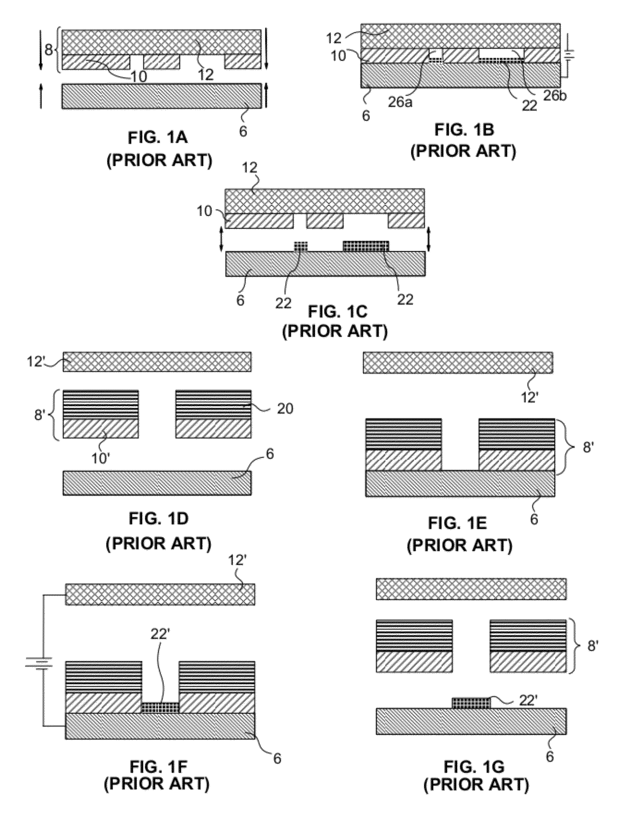
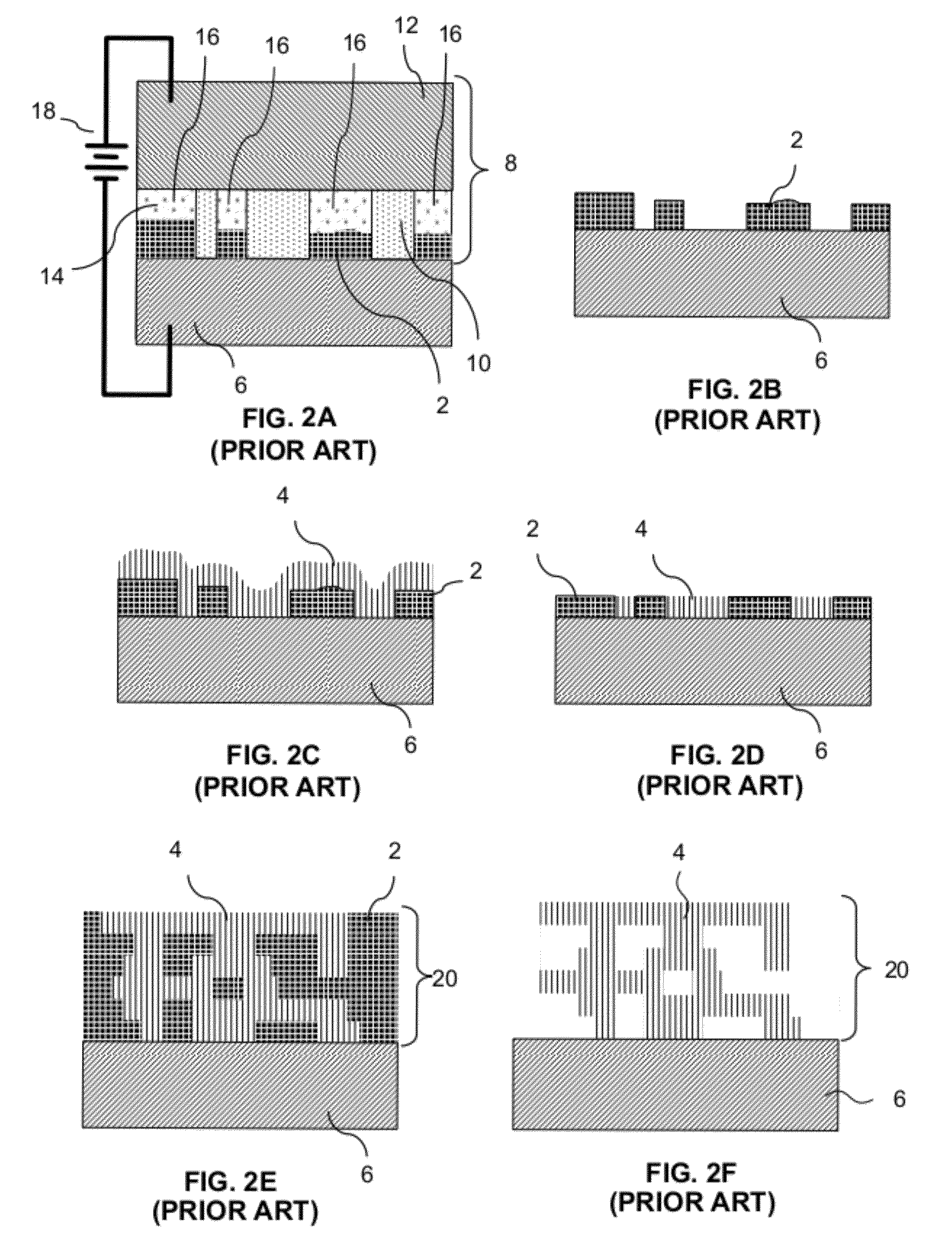
The CC mask plating process is distinct from a “through-mask” plating process in that in a through-mask plating process the separation of the masking material f

Method used


Image

  • Enhanced methods for at least partial in situ release of sacrificial material from cavities or channels and/or sealing of etching holes during fabrication of multi-layer microscale or millimeter-scale complex three-dimensional structures
  • Enhanced methods for at least partial in situ release of sacrificial material from cavities or channels and/or sealing of etching holes during fabrication of multi-layer microscale or millimeter-scale complex three-dimensional structures
  • Enhanced methods for at least partial in situ release of sacrificial material from cavities or channels and/or sealing of etching holes during fabrication of multi-layer microscale or millimeter-scale complex three-dimensional structures

Examples


second embodiment

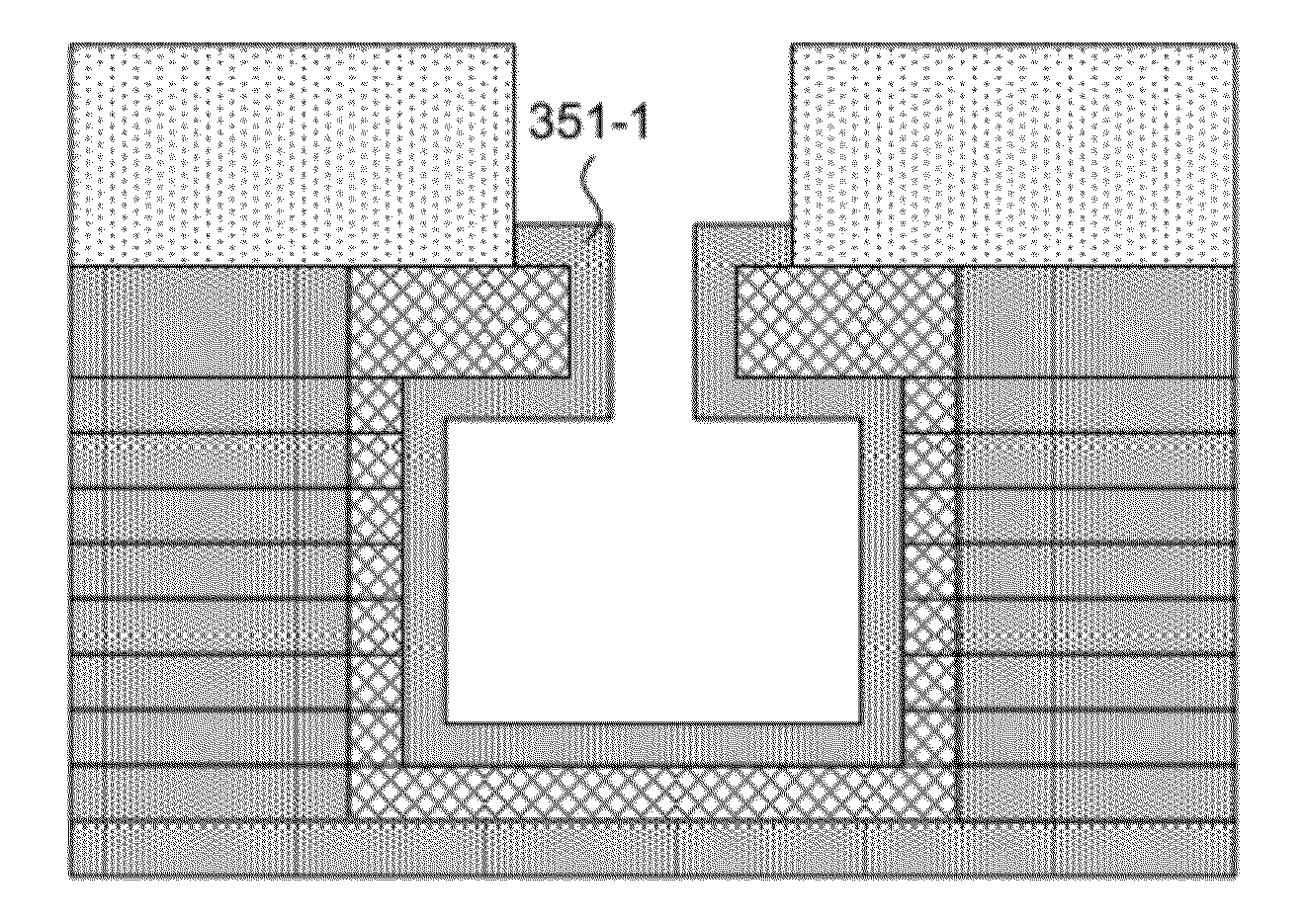
[0137]A process according to a variation of the second embodiment may include the following steps: (a) form the structure normally up through the penultimate capping layer with the exception that the penultimate capping layer may be initially planarized at a boundary level which is above a desired boundary level of the penultimate capping layer; (b) locate a mask on the penultimate layer with openings located over at least a portion of the etching openings (access region openings); (b) etch the sacrificial material from the etching openings and from at least a portion of passageway along a substantial length of the passage and to a depth that is greater (e.g. substantially greater) than a width of the etching openings; (c) with the mask still in place or a new patterned mask located in place or without a mask, deposit sacrificial material to fill the etching opening with it being understood that some plating into the released passage will occur but where the passage remains at least...

third embodiment

[0139]A process according to a variation of the third embodiment may include the following steps: (a) locate one or more etching openings in a passage capping layer that might otherwise be solid to provide an elongated access region; (b) form the structure normally up through the capping layer with the exception that the capping layer may be initially planarized at a boundary level which is above a desired boundary level of the capping layer; (c) locate a mask on the capping layer with openings located over at least a portion of the etching openings; (d) etch the sacrificial material from the etching openings and from at least a portion of passage along a substantial length of the passage and to a depth that is greater (e.g. substantially greater) than a width of the etching openings; (e) with the mask still in place or a new patterned mask located in place or with no mask in place, deposit structural material to fill the etching opening with it being understood that some plating in...


PUM

PropertyMeasurementUnit
Lengthaaaaaaaaaa
Lengthaaaaaaaaaa
Fractionaaaaaaaaaa

Abstract

Embodiments of the invention are directed to multi-layer, multi-material fabrication methods (e.g. electrochemical fabrication methods) which provide improved versatility in producing complex microdevices and in particular in removing sacrificial material from passages, channels, or cavities that are complex or that include etching access ports in their final configurations that are small relative to passage, channel, or cavity lengths. Embodiments of the present invention provide for removal of sacrificial material from these passages, channels or cavities using one or more initial or preliminary removal steps that occur prior to completion of the such passages that results from the completion of the layer forming steps. In some embodiments, first sacrificial material is replaced after a secondary solid sacrificial material after the initial removal step or steps. In other embodiments, the first sacrificial material is replaced after a liquid material after the initial removal step or steps. In some embodiments, desired structure formation may occur along or separately from one or more etchant directing manifolds that can force etchant into the passages, channels, and cavities.

Description

RELATED APPLICATIONS[0001]This application claims the benefit of U.S. Provisional Patent Application No. 61 / 222,077, filed Jun. 30, 2009. This application is incorporated herein by reference as if set forth in full herein.FIELD OF THE INVENTION[0002]The present invention relates generally to the field of multi-layer, multi-material fabrication of microscale and millimeter scale complex three-dimensional mechanical structures, parts, components, or fully or partially assembled components where each layer is formed from a plurality of deposited materials and more specifically to methods for forming such structures with passages, channels, cavities or the like which have sacrificial material removed from at least portions of such features before they are completely formed and / or which have openings that were used for multi-material etching of sacrificial material sealed by structural material during layer-by-layer fabrication of the structures. In some embodiments, fabrication may invo...

Claims


Application Information

Patent Timeline
IPC IPC(8): C23F1/22
CPCC25D1/003B81C1/00071
Inventor SMALLEY, DENNIS R.LOCKARD, MICHAEL S.COHEN, ADAM L.
Owner MICROFAB
Why Eureka
Try Eureka