Combustion-engined setting tool

a technology of combustion engine and setting tool, which is applied in the direction of manufacturing tools, nailing tools, stapling tools, etc., can solve the problems of high actuation force, high frictional force, and parts that are also subject to soiling, and achieve the effect of reliable cooperation between the two members

Active Publication Date: 2012-09-18
HILTI AG
View PDF18 Cites 13 Cited by
  • Summary
  • Abstract
  • Description
  • Claims
  • Application Information

AI Technical Summary

Benefits of technology

[0011]With magnetic means, it is possible to retain the plate-shaped member wear-free and without substantial technical expenses. The overpowering means, meanwhile, can be so formed that it overcomes the holding force of the magnetic means by magnetic means, e.g., by using switchable oppositely oriented magnets, or be so formed that it applies to the plate-shaped member a force acting in a direction opposite to the direction the holding force of the magnetic means acts and which is greater than the holding force of the magnetic means.
[0012]Advantageously, the overpowering means is actuated by the tool actuation switch. Thereby, it is possible to release the plate-shaped member shortly before ignition of the air-fuel mixture that fills the combustion chamber, whereby an optimally large turbulence can be generated by the movable plate-shaped member at the start of the combustion. E.g., there can be provided a slide connected with the actuation switch and which, upon actuation of the actuation switch, would lift the plate-shaped member off the magnetic means so far that the displacement force of displacing means which acts on the plate-shaped member, is sufficient to displace it through the combustion chamber.
[0015]It is advantageous when the displacing means is formed as a spring, and the setting tool has a press-on element which preloads the displacing means-forming spring against the displacement member. Thereby, the solution according to the present invention can be technically easily realized.
[0018]Advantageously, the guide member is formed as a bar-shaped member and is displaceable, at least partially in a first guide provided on the guide cylinder. Thereby, guidance of the plate-shaped member is achieved in a simple manner.
[0019]Advantageously, the displacement member is also formed as a bar-shaped member which is at least partially displaceable in a second guide provided on the press-on element of the displacement member relative to the guide member and, thereby, a reliable cooperation of the two members is achieved.
[0020]It is advantageous when the magnetic means is formed of at least two magnetic elements for holding the plate-shaped member. Thereby, a uniform application of the holding force to the plate-shaped member is insured.

Problems solved by technology

The drawback of the setting tool described above consists in that the latch mechanism consists of a large number of parts interacting with each other, generating frictional forces.
The parts are also subjected to soiling and require narrow tolerances.
All this can lead to high actuation forces or even to the failure of the latch mechanism

Method used


Image

  • Combustion-engined setting tool
  • Combustion-engined setting tool
  • Combustion-engined setting tool

Examples


Embodiment Construction

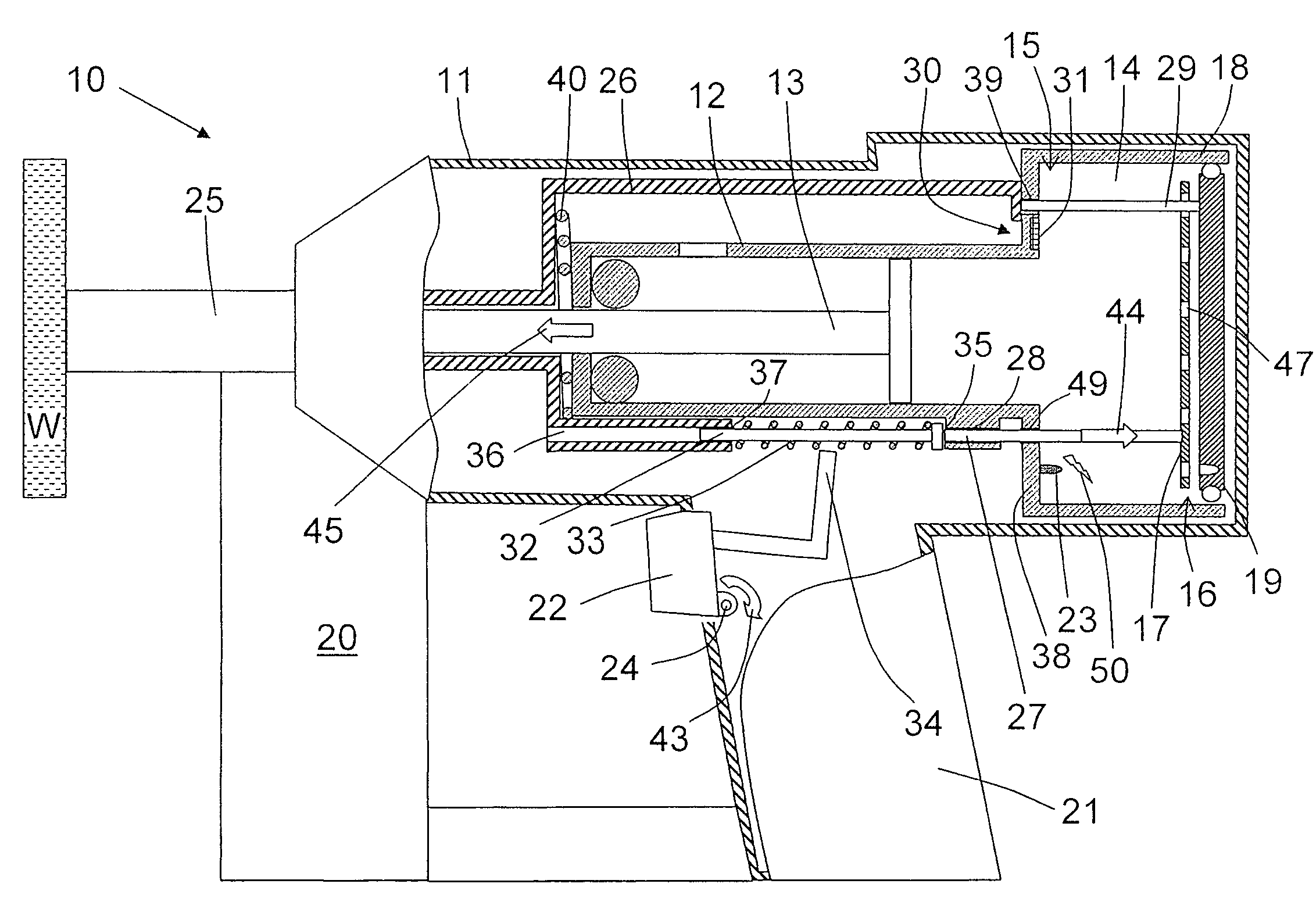
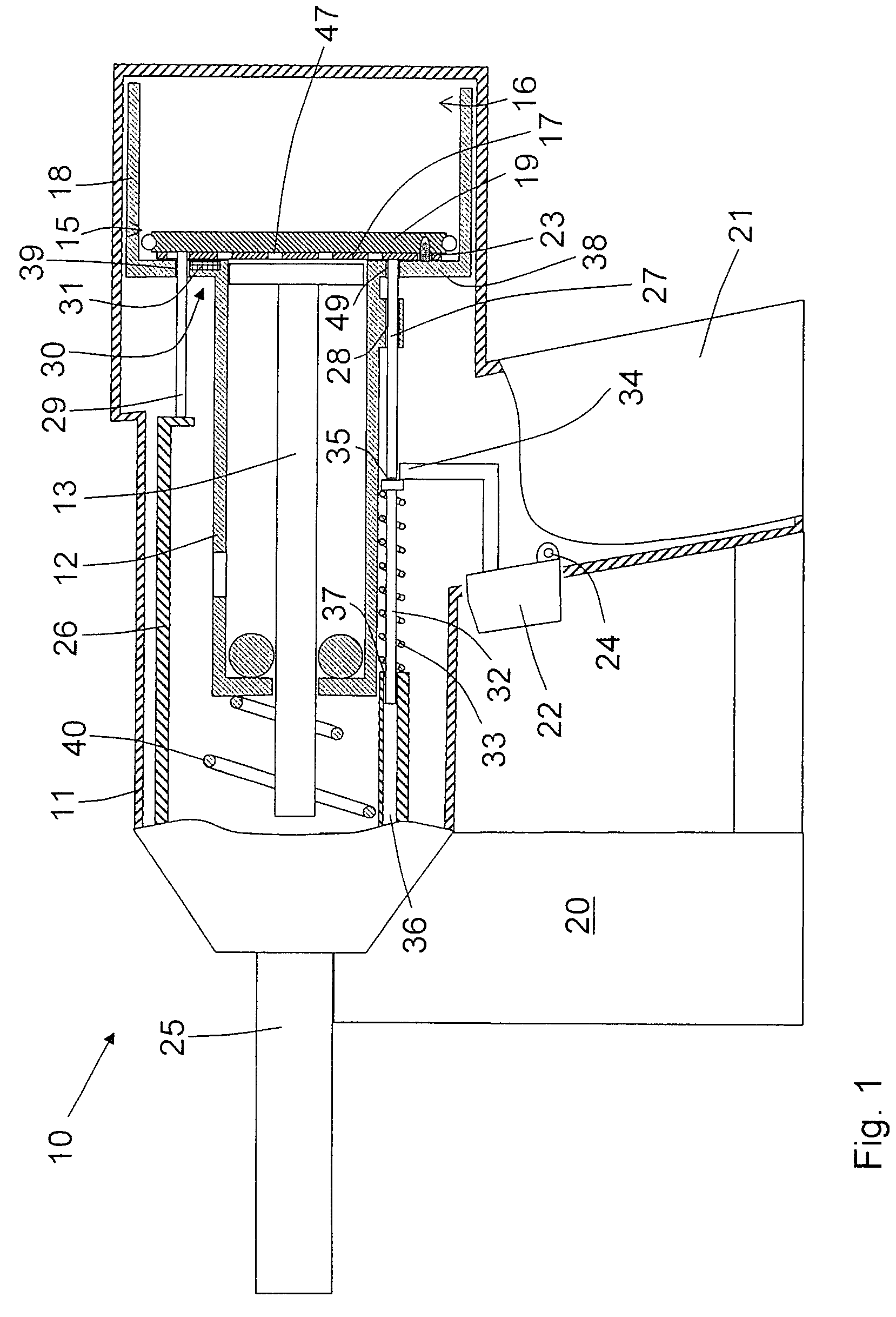
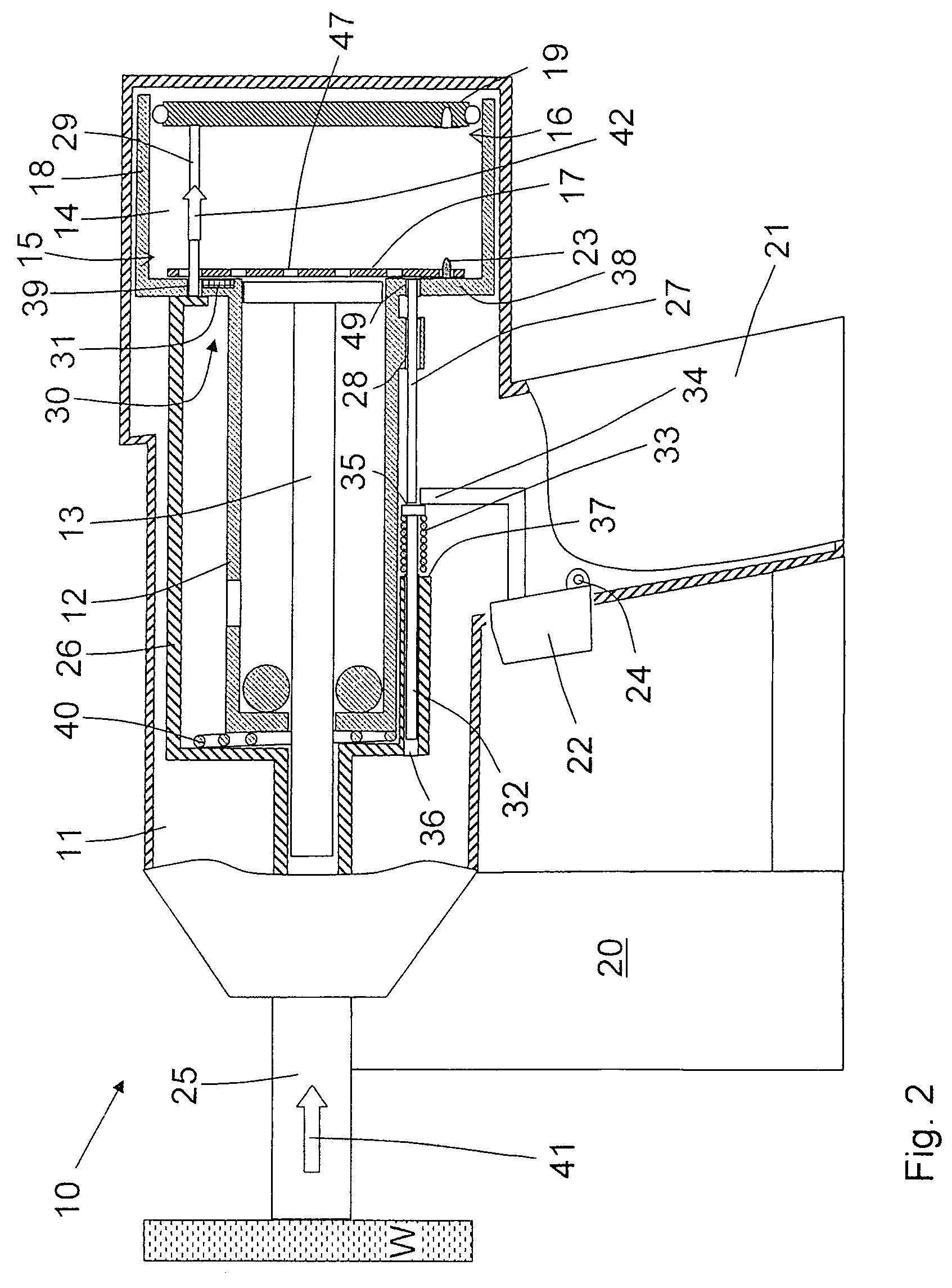
[0027]A setting tool 10 according to the present invention, which is shown in FIGS. 1-3, is driven with fuel gas that is stored in a fuel reservoir, not shown, in form of a liquefied gas. Instead of the fuel gas, a liquid fuel, which can be evaporated, such as, e.g., alcohol or gasoline can be used. The setting tool 10 includes a housing 11 and a setting mechanism which is located in the housing 11 and with which a fastening element, not shown, can be driven in a workpiece W when the setting tool 11 is pressed against the workpiece W and is actuated. The setting mechanism includes, among others, a combustion chamber 14 for an oxidant-fuel gas mixture, a guide cylinder 12 in which a setting piston 13 is supported for an axial displacement, and a bolt guide 25 that adjoins the guide cylinder at its end remote from the combustion chamber 14. The bolt guide 25 serves for guiding the fastening element such as, e.g., a bolt or a nail, and forms simultaneously a functional part of a press-...


PUM


Abstract

A combustion-engined setting tool for driving fastening elements such as, e.g., nails, bolts, or pins in a workpiece, includes a plate-shaped member (17) axially displaceable in the tool combustion chamber (14), a member (33) for displacing the plate-shaped member (17), a holding device (30) for retaining the plate-shaped member (17) at an axial end (15) of the combustion chamber (14) against action of the displacing member (33), with the holding device (30) having magnetic elements (31) for producing a holding force for retaining the plate-shaped member (17) and a device for overpowering the holding force produced by the magnetic elements (31).

Description

BACKGROUND OF THE INVENTION[0001]1. Field of the Invention[0002]The present invention relates to a setting tool for driving fastening elements such as, e.g., bolts, nails, pins in a constructional component and including a combustion chamber for an oxidant-fuel gas mixture, a guide cylinder adjoining the combustion chamber at one of its ends, a setting piston displaceable in the guide cylinder for driving a fastening element in the workpiece, a plate-shaped member axially displaceable in the combustion chamber for creating turbulence therein, means for displacing the plate-shaped member, and a holding device for retaining the plate-shaped member at an axial end of the combustion chamber against action of the displacing means.[0003]2. Description of the Prior Art[0004]Setting tools of the type described above are driven with gaseous fuels or liquid fuels which are evaporated before combustion. The setting energy for driving in a fastening element is obtained by combustion of an oxida...

Claims


Application Information

Patent Timeline
Patent Type & Authority Patents(United States)
IPC IPC(8): B25C1/08
CPCB25C1/08
Inventor ZAHNER, MARIOWOLF, IWANBOENIG, STEFAN
Owner HILTI AG
Why Eureka
Try Eureka