
Transducer for sensing actual or simulated body sounds

a transducer and body technology, applied in the field of simulated body sounds, can solve the problems of distortion and noise, distortion and noise, and the process of listening to and analyzing body sounds is often difficult to learn, and achieves constant charge, high resistance, and change in capacitance.

Inactive Publication Date: 2012-09-25
SMITH CLIVE LEONARD
View PDF2 Cites 21 Cited by
  • Summary
  • Abstract
  • Description
  • Claims
  • Application Information

AI Technical Summary

Benefits of technology

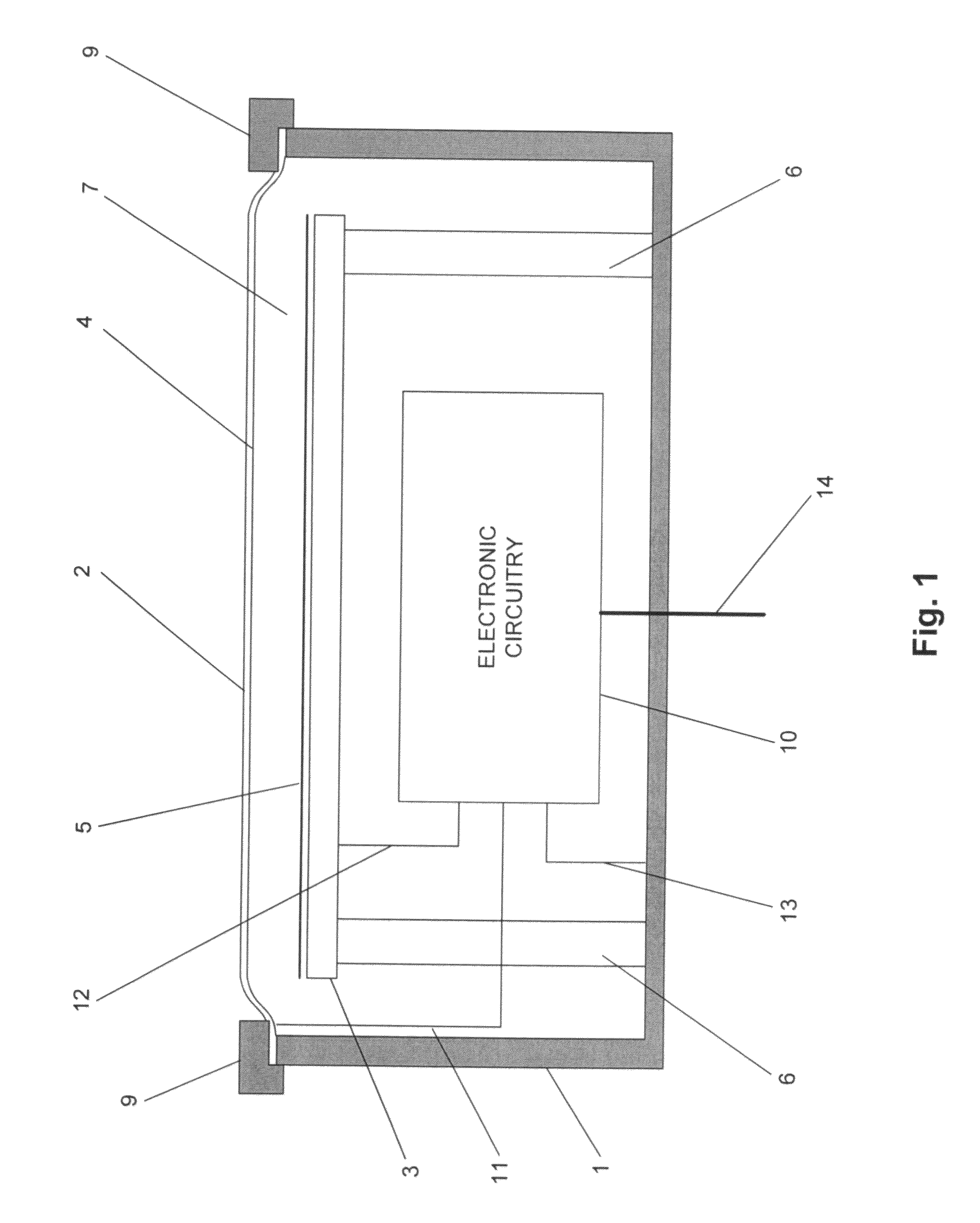
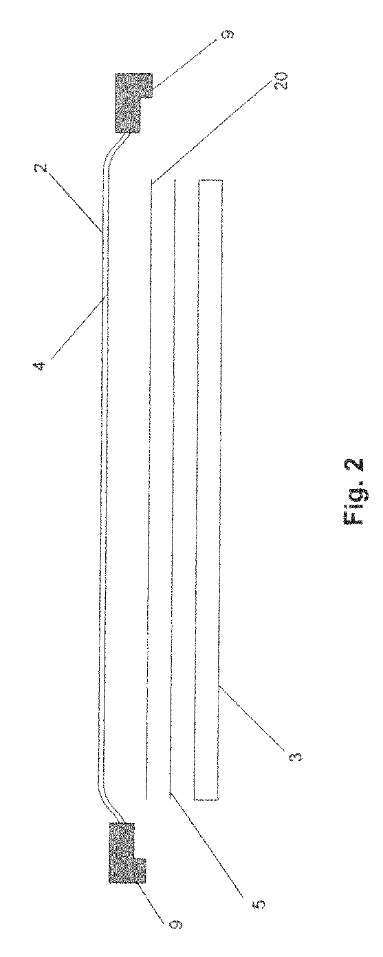
[0019]A fundamental advantage of the present invention is that diaphragm movement is not impeded by the acoustic-to-electrical conversion means, since there is a spacing between the diaphragm and other transducer elements. Therefore, the acoustic characteristics of the diaphragm are maintained, and the sound more closely resembles an acoustic stethoscope sound, which is familiar to the current user base of doctors, nurses and others. This is a unique aspect of this invention, in that other acoustic sensors do not require the amount of diaphragm motion required for a contact-type sensing device such as a stethoscope. Thus while other applications require only tens of microns of spacing, and the diaphragms typically move only a few microns when in use, this invention allows for movement of the diaphragm of more than 0.1 mm. Depending on the stiffness of the diaphragm, pressure against the body can result in 0.1 mm, 0.2 mm, 0.5 mm or even 1 mm of diaphragm displacement due to pressure.
[0021]The first embodiment utilizes a capacitive sensing method. Capacitive acoustic sensors have been disclosed and are in common use in high performance microphones and hydrophones. However, the present invention uses the stethoscope diaphragm itself as one plate of the capacitive sensor which touches the body surface directly. This method of direct contact capacitive sensing of body sounds as described, is unique.
[0022]The sensor comprises a movable diaphragm with a conductive plane or surface, and a co-planar conductive surface (electrode or plate) placed behind the diaphragm, with a space or electrolyte between the two elements. The diaphragm's conductive surface, in conjunction with the second conductive plate, form a capacitor. Movement of the diaphragm due to motion or sound pressure modulates the distance between the diaphragm and plate, producing a change in capacitance. One unique aspect of the invention lies in the fact that the stethoscope diaphragm forms one plate of the capacitor.
[0023]A feature of the invention is that the diaphragm, being the same element that makes contact with the body, is primarily sensitive to sounds emanating from the body, rather than sound transmitted through the air from ambient noise. By making contact with the body, the acoustic impedance of the sensor becomes matched to that of the body, rather than the surrounding air. Therefore, the capacitance change due to diaphragm motion is primarily due to body sounds, rather than overall ambient noise.
[0024]While a number of means are available for converting the capacitance variation to an electrical signal, the preferred embodiment performs this conversion by charging the capacitance formed by the diaphragm-plate combination to a high DC voltage, via a high resistance. This produces a somewhat constant charge on the capacitor. Movement of the diaphragm then produces a variation in the capacitance. If the capacitor charge is fixed, and the capacitance varies with time, a small AC variation in capacitance voltage is produced. This is sensed by a high-impedance amplifier, which is designed to detect the AC changes in capacitance voltage while avoiding rapid discharge of the capacitor.
[0025]A second method for detecting capacitance change is to employ the same diaphragm-plate capacitance in a high-frequency resonant or oscillation circuit, and detect changes in oscillation frequency produced by changes in the time constant of the capacitive circuit.

Problems solved by technology

The procedures for listening to and analyzing body sounds, called auscultation, is often difficult to learn due to the typically low sound volume produced by an acoustic stethoscope.
However, such devices suffer from distortion and ambient noise pickup.
The distortion and noise are largely due to the performance of the acoustic-to-electrical transducers, which differ in operation from the mechanical diaphragms used in acoustic stethoscopes.
The existence of two diaphragms, and the intervening air path, result in excess ambient noise pickup by the microphone, as well as inefficient acoustic energy transfer.
However, these methods are often just compensations for the fundamental inadequacies of the acoustic-to-electrical transducers.
The problem with this sensor is that the conversion mechanism produces signal distortion compared with sensing the pure motion of the diaphragm.
The problem with such sensors is that they restrict the mechanical movement of the diaphragm by imposing a mechanical load on the diaphragm.
Thus placing sensors in contact with the diaphragm restrict its movement and change its acoustic properties and hence the sounds quality.
A capacitive, magnetic or optical microphone placed behind a stethoscope diaphragm would suffer from the same ambient noise and energy transfer problems that occur with any other microphone mounted behind a stethoscope diaphragm.
Body sound transducers and stethoscopes in particular have been plagued by pickup of ambient noise in addition to body sounds.
Thus stethoscope chestpieces have closed cavities, which result in standing waves and acoustic resonance within the cavity.
Such acoustics tend to exacerbate the effects of ambient noise which reverberates in the chestpiece.
Learning auscultation has always been a difficult process.

Method used


Image

  • Transducer for sensing actual or simulated body sounds
  • Transducer for sensing actual or simulated body sounds
  • Transducer for sensing actual or simulated body sounds

Examples


Embodiment Construction

[0076]The preferred embodiments are divided into three categories—(a) Capacitive Sensor embodiments, (b) Magnetic Sensor embodiments, and (c) Optical Sensor embodiments. These are all discussed separately below.

[0077]A fundamental aspect of the invention, covering all embodiments, is (a) that the diaphragm makes direct contact with the body for sound sensing, (b) the diaphragm is an integral part of the acoustic-to-electric transducer mechanism rather than simply transmitting sound waves via air to a second acoustic-to-electrical transducer i.e. in this invention the diaphragm motion itself is converted to an electrical signal and (c) the mechanical structure of transducer elements other than the diaphragm do not make direct contact with the diaphragm and hence the conversion means does not impede diaphragm motion or place a mechanical load on the diaphragm.

[0078]The benefit of this method is that the acoustic properties of the diaphragm are essentially the same as those of an acous...


PUM


Abstract

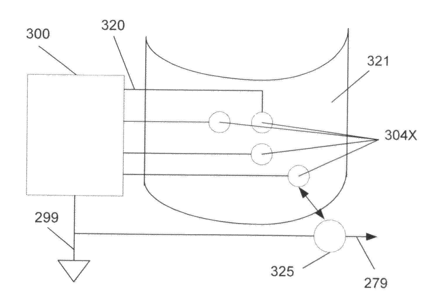
A transducer system is disclosed for detecting actual or simulated body sounds. An audio signal generation and detection system is disclosed for the purposes of simulating the medical examination of a patient or simulating the listening of sounds seeming to emanate from a live or inanimate body. A signal generator sets up a voltage potential at an electrode physically attached to the body, or electrically connected to a body, thereby setting up a voltage potential on a surface area of the body. An electric field potential sensor or a capacitive electrical sensor placed in proximity to the electrode or body surface then detects the voltage potential. The signals produced by the signal generator can represent heart, lung, bowel or other sounds and the electrical sensor can take the physical form of a listening device such as a stethoscope, thereby creating a simulation of listening to body sounds for medical diagnostic purposes.

Description

CROSS REFERENCE TO RELATED APPLICATIONS[0001]This application is a continuation-in-part of U.S. patent application Ser. No. 10 / 747,863 filed Dec. 23, 2003, which is a continuation-in-part of U.S. patent application Ser. No. 10 / 730,750 filed Dec. 8, 2003, which is a continuation of U.S. patent application Ser. No. 10 / 328,768 filed Dec. 23, 2002, now U.S. Pat. No. 6,661,897, which is a continuation in part of U.S. patent application Ser. No. 09 / 431,717 filed Oct. 28, 1999, now U.S. Pat. No. 6,498,854, all of which are incorporated herein by reference in their entirety.FIELD OF THE INVENTION[0002]The present invention relates to sensing body sounds and simulated body sounds, and to acoustic-to-electrical and electrical transducers used for sensing body sounds or simulated body sounds, especially in stethoscopes.BACKGROUND OF THE INVENTION[0003]Stethoscopes are widely used by health professionals to aid in the detection of body sounds. The procedures for listening to and analyzing body ...

Claims


Application Information

Patent Timeline
Patent Type & Authority Patents(United States)
IPC IPC(8): A61B7/04
CPCA61B7/04G10K15/02A61B2560/0209A61B2562/0204
Inventor SMITH, CLIVE LEONARD
Owner SMITH CLIVE LEONARD
Learn More