Method for Manufacturing Glass Sealed Body and Method for Manufacturing Light-Emitting Device

a technology of glass sealing and manufacturing method, which is applied in the manufacture of electrode systems, manufacturing tools, and electric discharge tubes/lamps, etc., can solve the problems of insufficient sealing of the portion, broken sealing of the applied portion, and paste-like powdered glass, so as to reduce the amount of paste, reduce the step, and increase the air tightness of the resulting closed space

Inactive Publication Date: 2012-11-15
SEMICON ENERGY LAB CO LTD
View PDF28 Cites 37 Cited by
  • Summary
  • Abstract
  • Description
  • Claims
  • Application Information

AI Technical Summary

Benefits of technology

[0020]Further, in the case where a terminal of an electrode is led from the light-emitting element, a step caused by the partition may be reduced in such a manner that the amount of paste is decreased or the paste is not applied at a portion overlapping with the terminal, whereby the airtightness of a resulting closed space can be increased. As a method for reducing the step, for example, a method in which the partition is formed of the paste and then a flat plate is pressed against the partition, whereby a surface of the partition is planarized, a method in which the amount of paste is reduced only over the terminal to reduce the amount of paste which is applied to the terminal portion, or the like is given.
[0021]Further, a partition of the frit glass may also be formed over the second glass substrate in addition to the first glass substrate. In that case, when local heating is performed in the state where their respective frit glasses are disposed in close contact with each other, the welding can be further easily performed, which is preferable. Alternatively, one partition provided for the first glass substrate or the second glass substrate may surround the other partition.
[0022]Note that in this specification, the paste includes powdered glass and a binder. The binder in this specification serves to increase the viscosity by jointing particles of powdered glass. Further, the frit glass in this specification is a fusion of powdered glass. Further, the rapid heater in this specification refers to a heater by which the temperature can be increased by 200° C. or higher at 10 seconds.
[0023]According to one embodiment of the present invention, a method for manufacturing a glass sealed body having a uniform partition, in which the sealing is hardly broken and a method for manufacturing a light-emitting device provided with the glass sealed body can be provided. Since such a glass sealed body is extremely strong against impact or external force, the airtightness can be maintained even when it is used under a severe environment. For example, even when a light-emitting element including an organic EL element, which is sensitive to the air including oxygen, moisture, or the like is used outdoors while being carried, the characteristics of the light-emitting device can be maintained for a long time.

Problems solved by technology

However, since the paste-like powdered glass is discharged from the nozzle to draw a closed curve to form in the partition, there is a high possibility that continuity of the paste-like powdered glass is broken at a portion where the closed curve is closed and thereby sealing of the portion becomes insufficient.
Further, even when slight impact or external force is applied to the glass sealed body manufactured in this manner, there is a possibility that the sealing is broken from the applied portion.

Method used


Image

  • Method for Manufacturing Glass Sealed Body and Method for Manufacturing Light-Emitting Device
  • Method for Manufacturing Glass Sealed Body and Method for Manufacturing Light-Emitting Device
  • Method for Manufacturing Glass Sealed Body and Method for Manufacturing Light-Emitting Device

Examples


embodiment 1

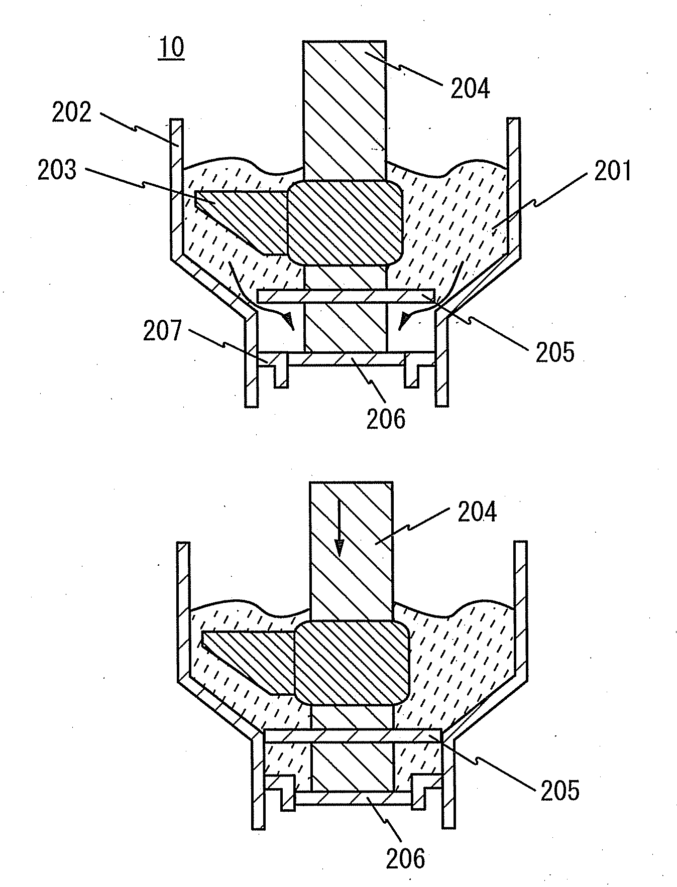
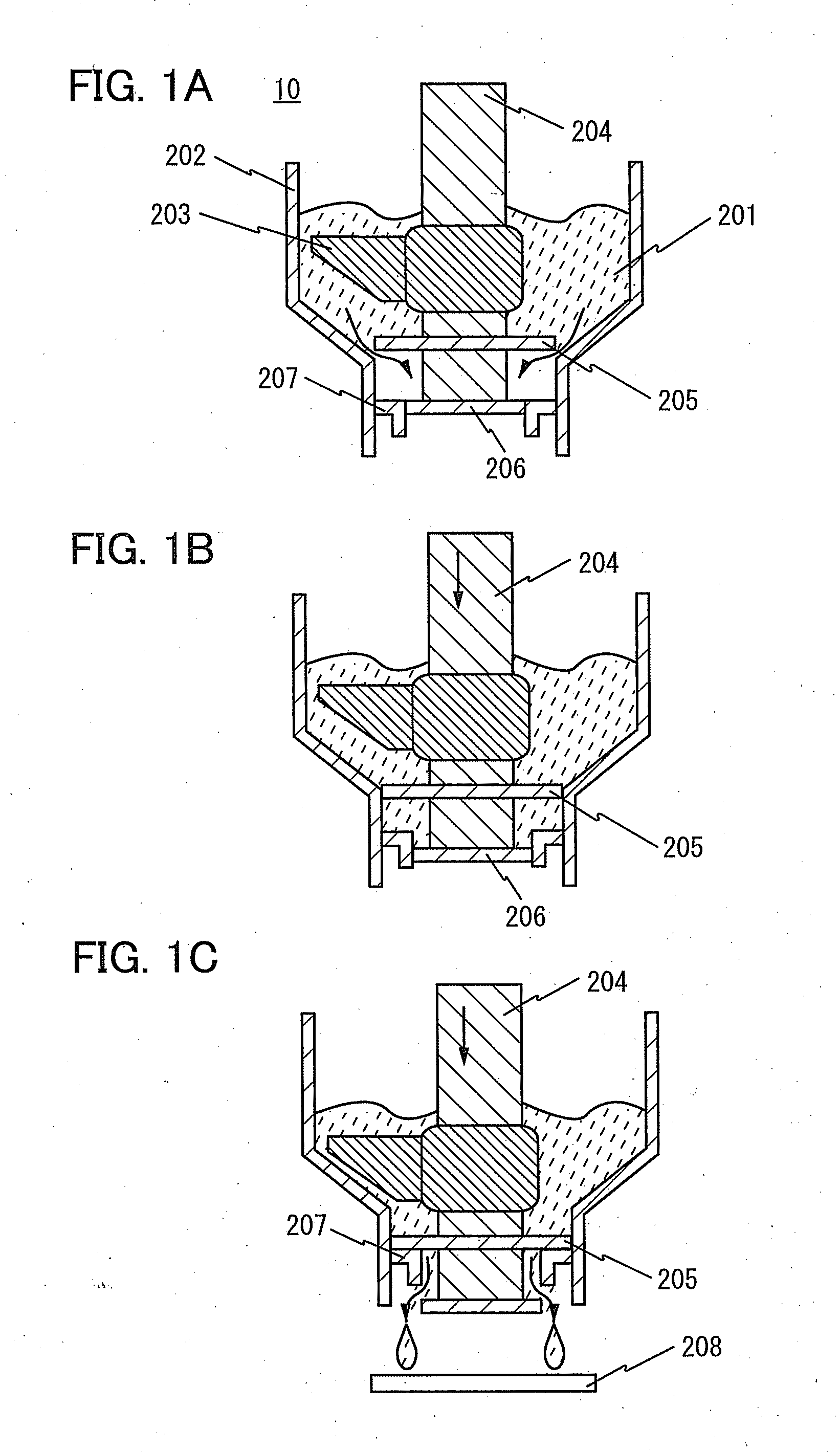
[0043]In this embodiment, one embodiment of a method for manufacturing a glass sealed body will be described with reference to FIGS. 1A to 1C, FIGS. 2A to 2C, FIGS. 3A and 3B, and FIGS. 4A and 4B. FIGS. 1A to 1C illustrate an example of a device 10 for discharging a paste formed in an annular shape. In this specification, the annular shape refers to a closed curve with a large width and may include a corner, a straight line, or the like, in addition to a curve line. A paste 201 is contained in a container 202. The paste 201 including powdered glass and a binder is mixed to be homogeneous with a stirrer 203 that rotates about a control stick 204. Although the stirrer 203 has one impeller in FIGS. 1A to 1C, it may have a plurality of impellers. Alternatively, in the case where the paste 201 is mixed in advance with an external stirrer, the stirrer can be omitted in the device 10.

[0044]It is preferable that the powdered glass include one or more compound selected from a group of, for e...

embodiment 2

[0053]A method for manufacturing a light-emitting device which is one embodiment of the present invention and includes the glass sealed body described in Embodiment 1 will be described with reference to FIGS. 5A to 5C and FIGS. 6A to 6C.

[0054]A light-emitting element such as an organic EL element includes an electrode for supplying power and a terminal can be led from the electrode to be connected to an external power source. However, a projected portion is formed in a position where the terminal is provided; therefore, airtightness of sealing may become worse. An example of a method for suppressing an adverse effect due to the projected portion will be described with reference to FIGS. 6A to 6C.

[0055]First, as illustrated in FIG. 5A, an organic EL element 125 is provided over a glass substrate 100. The organic EL element 125 has a stacked structure in which an anode, a light-emitting layer, and a cathode are stacked in this order over the glass substrate 100, for example. Note that...

embodiment 3

[0065]Examples of optical systems applied to the flash lamp described in the above embodiments will be described with reference to FIGS. 7A and 7B. In FIGS. 7A and 7B, the partition 122 without a joint portion according to one embodiment of the present invention is formed over the glass substrate 100 and the state where the glass substrate 101 and the partition 122 are disposed in close contact with each other is shown.

[0066]As illustrated in FIG. 7A, the flash lamp 123 is covered with a cylindrical mirror 127, whereby light which is extended to the surroundings can be collected in one direction. For example, the cross-sectional shape of the cylindrical mirror 127 in a direction parallel to the drawing of FIGS. 7A and 7B is an ellipse. Further, the flash lamp 123 is placed at a focal point of the ellipse and the partition 122 is placed at the other focal point of the ellipse, whereby light can be effectively collected to the partition 122.

[0067]As another example, as illustrated in ...


PUM

PropertyMeasurementUnit
temperatureaaaaaaaaaa
wavelengthaaaaaaaaaa
light emission timeaaaaaaaaaa

Abstract

In a method for manufacturing a glass sealed body, a paste including powdered glass and a binder is discharged from an outlet whose shape is a closed curve to fowl a partition whose shape is a closed curve over a first glass substrate; the partition is heated so that the binder is volatilized and the powdered glass is fused to be a frit glass; and the frit glass and a second glass substrate are heated while disposing in close contact with each other, so that the frit glass and the second glass substrate are welded together to form a closed space by the frit glass, the first glass substrate, and the second glass substrate. A light-emitting element is sealed with the glass sealed body, so that the sealing is hardly broken even when impact or external force is applied.

Description

BACKGROUND OF THE INVENTION[0001]1. Field of the Invention[0002]The present invention relates to a method for manufacturing a sealed body by which a device is protected against the air. One embodiment of the disclosed invention relates to a method for manufacturing a glass sealed body and a method for manufacturing a light-emitting device provided with the glass sealed body.[0003]Note that in this specification, the light-emitting device refers to a display device such as an organic EL display device or a light source (a lighting device) such as lighting or a sign (e.g., a traffic light or a warning light). Further, the device includes a light-emitting element.[0004]2. Description of the Related Art[0005]In recent years, light-emitting devices which have electroluminescence (hereinafter, referred to as EL) elements using EL as self-luminous light-emitting elements have been actively researched. The light-emitting devices are used for organic EL display devices, organic EL lighting d...

Claims


Application Information

Patent Timeline
Patent Type & Authority Applications(United States)
IPC IPC(8): C03B23/20
CPCH01L51/5246H01J9/248C03C27/06H10K50/8426
Inventor TANAKA, KOICHIRO
Owner SEMICON ENERGY LAB CO LTD
Why Eureka
Try Eureka