Unmanned biplane for airborne reconnaissance and surveillance having staggered and gapped wings

a technology of unmanned aerial vehicles and wing wings, which is applied in the direction of canard-type aircraft, wing shapes, transportation and packaging, etc., can solve the problems of many types of ground surveillance missions that are beyond the practical capabilities of a human observer, and many types of ground surveillance missions that are inherently hazardous, etc., and achieves the effect of convenient assembly

Inactive Publication Date: 2006-05-18
MISSION TECH
View PDF13 Cites 36 Cited by
  • Summary
  • Abstract
  • Description
  • Claims
  • Application Information

AI Technical Summary

Benefits of technology

[0008] It is an object of the present invention to provide an unmanned aerial...

Problems solved by technology

Unmanned aerial vehicles have been complex and difficult to operate in their intended environment.
Many types of ground surveillance missions are beyond the practical capabilities of a human observer due to the inability to see over a hill.
For example, missions that are inherently hazardous or that require surveillance at multiple sites over a short time span.
Many of these UAVs, however,...

Method used


Image

  • Unmanned biplane for airborne reconnaissance and surveillance having staggered and gapped wings
  • Unmanned biplane for airborne reconnaissance and surveillance having staggered and gapped wings
  • Unmanned biplane for airborne reconnaissance and surveillance having staggered and gapped wings

Examples


Embodiment Construction

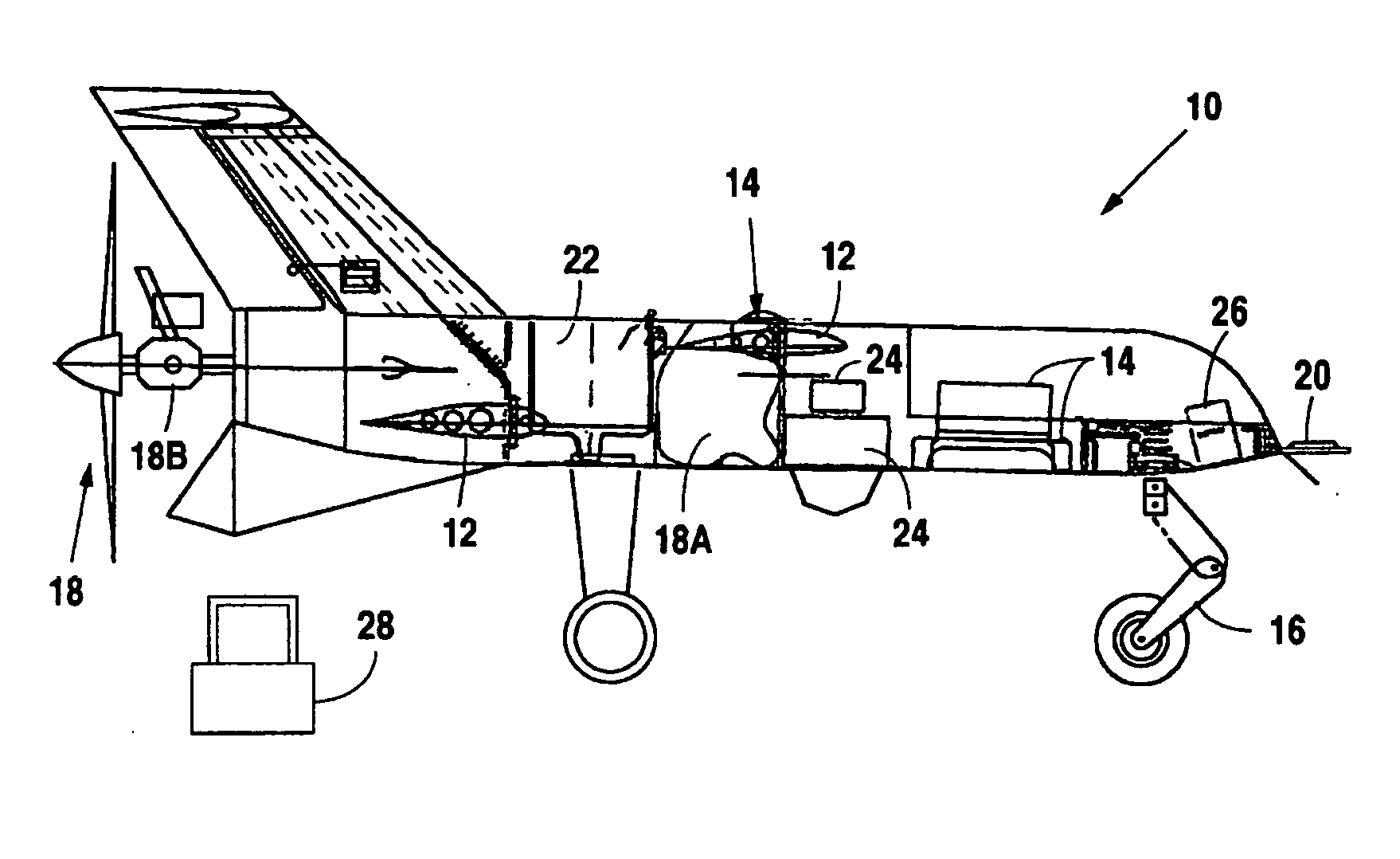
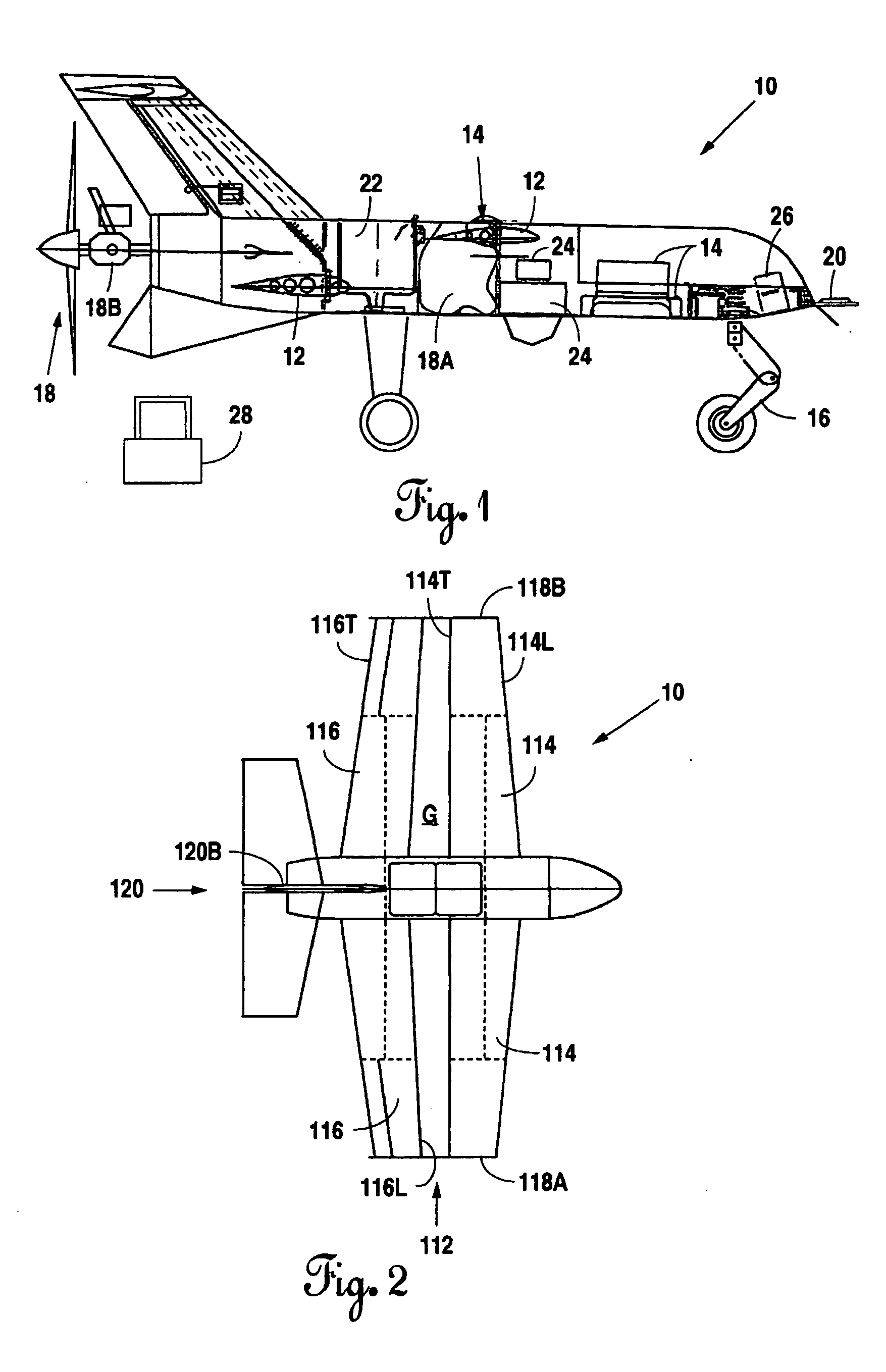
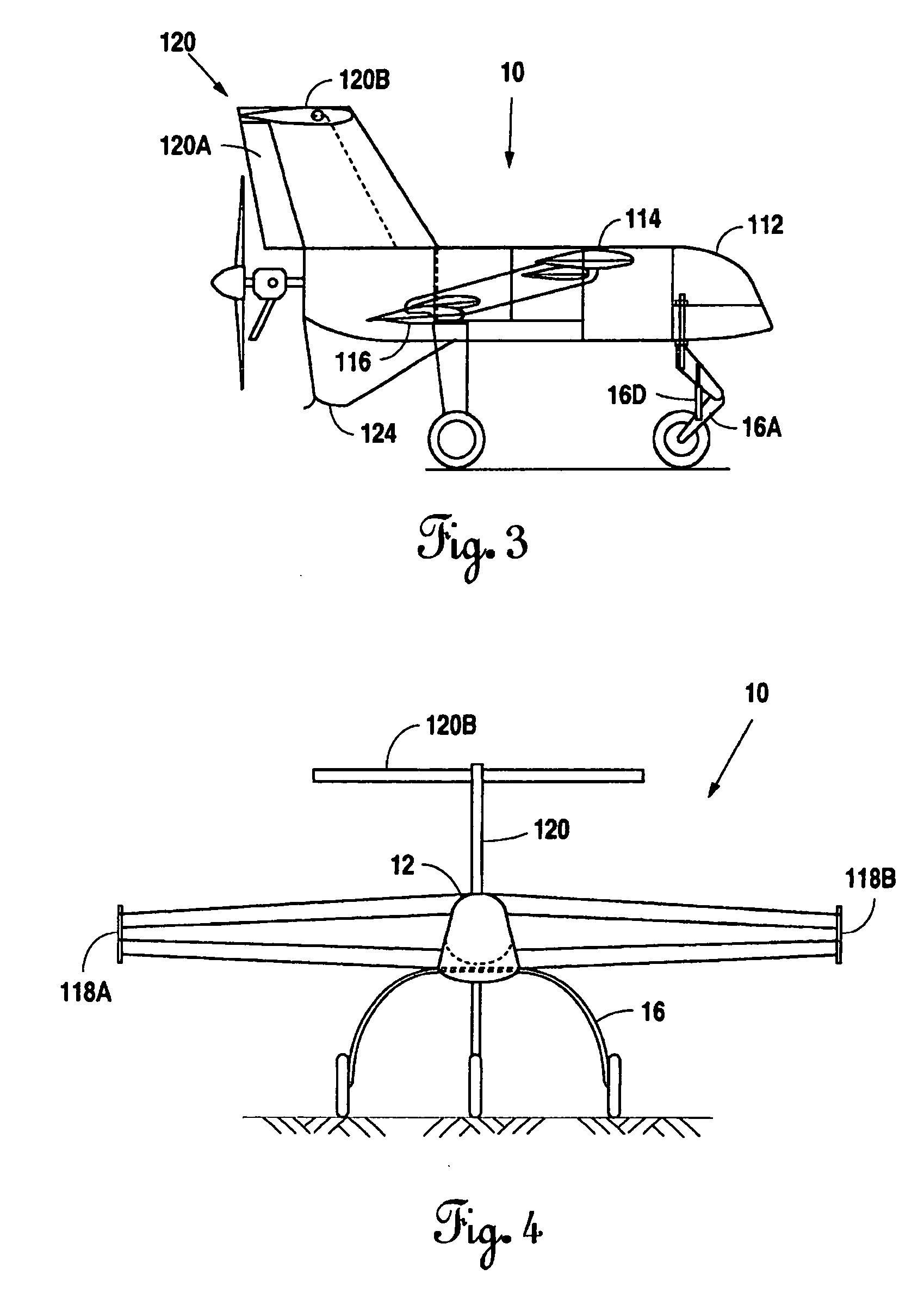
[0029] Referring to the Figures, the present invention is herein described as an unmanned airborne reconnaissance vehicle. FIG. 1 illustrates Applicants' UAV system (10), the system including an airframe (12), a data link system (14), an undercarriage (16), a propulsion system (18) including a fuel system bladder (18A), a power plant (18B), avionics (20), and a recovery system (22), such as a parachute for deployment from an onboard container. In one embodiment, the UAV system (10) of the present invention includes at least one payload (24), such as an onboard infrared camera, and an electrical system (26). In one embodiment, the present invention is equipped with one or more ground control stations (28) which may include ground support equipment.

[0030] The airframe (12) utilized by the present invention will be discussed in greater detail below, but is designed to provide a stable platform for reconnaissance and surveillance equipment or deliverance of varied payloads and / or bioch...


PUM


Abstract

The present invention provides an unmanned airborne reconnaissance vehicle having a fuselage, a forward wing pair and a rearward wing pair vertically separated by a gap and staggered fore and aft therebetween such that a general biplane configuration is formed. The present invention provides a pair of wing tip plates for joining the wing tips of the forward and rearward wings. The unmanned airborne reconnaissance vehicle of the present invention includes a power plant to propel the vehicle through the air and a generally T-shaped tail having a vertical stabilizer including a rudder and a full span elevator.

Description

[0001] This patent application claims priority from pending application Ser. No. 10 / 625,399, filed on Jul. 23, 2003, which claimed priority from application Ser. No. 10 / 143,603 filed on May 10, 2002 and issued as U.S. Pat. No. 6,626,398 on Sep. 30, 2003, which claimed priority from provisional patent application Ser. No. 60 / 292,842 filed on May 10, 2001. This patent application also claims priority from pending application Ser. No. 10 / 620,026, filed on Jul. 15, 2003, which claimed priority from provisional patent application Ser. No. 60 / 292,842 filed on May 10, 2001. [0002] This patent application incorporates by reference provisional patent application Ser. No. 60 / 292,842; application Ser. Nos. 10 / 143,603, 10 / 620,026, and 10 / 625,399; and U.S. Pat. No. 6,626,398 as if they were each fully printed herein.FIELD OF THE INVENTION [0003] The present invention is directed to an unmanned aerial vehicle in the nature of a biplane, that is portable, modular and includes a forward pair of win...

Claims


Application Information

Patent Timeline
IPC IPC(8): B64C39/12B64C13/20
CPCB64C1/26B64C3/14B64C13/20B64C39/024B64C39/08B64C2201/021B64C2201/102B64C2201/104B64C2201/123B64C2201/126B64C2201/127B64C2201/128B64C2201/141B64C2201/146B64C2201/165B64C2201/185B64U30/10B64U10/25B64U2101/60B64U2201/10B64U70/83B64U50/13B64U2201/20B64U30/14B64U2101/31B64U30/12B64U2101/00B64U2101/30
Inventor COX, BEVERLYDEWS, HAMPTONNYROTH, NICHOLAS
Owner MISSION TECH
Why Eureka
Try Eureka