Antenna apparatus and communication terminal

a technology of communication terminals and antennas, which is applied in the structure of antenna earthings, screened loop antennas, radiating elements, etc., can solve the problems of insufficient space for an antenna in the casings of communication terminals, and so as to reduce the deterioration of antenna characteristics, and improve the effect of antenna characteristics

Active Publication Date: 2013-08-15
MURATA MFG CO LTD
View PDF3 Cites 37 Cited by
  • Summary
  • Abstract
  • Description
  • Claims
  • Application Information

AI Technical Summary

Benefits of technology

[0008]Preferred embodiments of the present invention provide an antenna apparatus capable of maintaining a radiation characteristic of a booster antenna connected to a ground conductor and a communication terminal including the antenna apparatus.
[0014]With this configuration, the booster antenna can be electrically connected to the ground conductor and the need to newly dispose a booster antenna is eliminated.
[0016]With this configuration, the booster antenna can be electrically connected to the ground conductor and the need to newly dispose a booster antenna is eliminated.
[0018]With this configuration, the length of a path for a current that does not contribute radiation, that is, a current passing through the periphery of the slit and the booster antenna, is significantly reduced. This leads to the reduction in a loss.
[0020]According to a preferred embodiment of the present invention, since a circuitous path for a current is not provided in an area in which the density of a current flowing through a booster antenna is high, a loss becomes small and the deterioration of an antenna characteristic due to the connection of the booster antenna to the ground rarely occurs. As a result, an antenna apparatus with a long communication distance can be obtained. Furthermore, a directivity toward a high current density area can be achieved.

Problems solved by technology

On the other hand, since communication terminals decrease in size and increase in functionality, there is not sufficient space for an antenna in the casings of the communication terminals.
However, in a case where the ground of the printed circuit board and the metal casing are connected, an antenna characteristic may be deteriorated in accordance with a connection method.

Method used


Image

  • Antenna apparatus and communication terminal
  • Antenna apparatus and communication terminal
  • Antenna apparatus and communication terminal

Examples


first preferred embodiment

[0048]An antenna apparatus according to the first preferred embodiment of the present invention and a communication terminal according to the first preferred embodiment will be described with reference to the accompanying drawings.

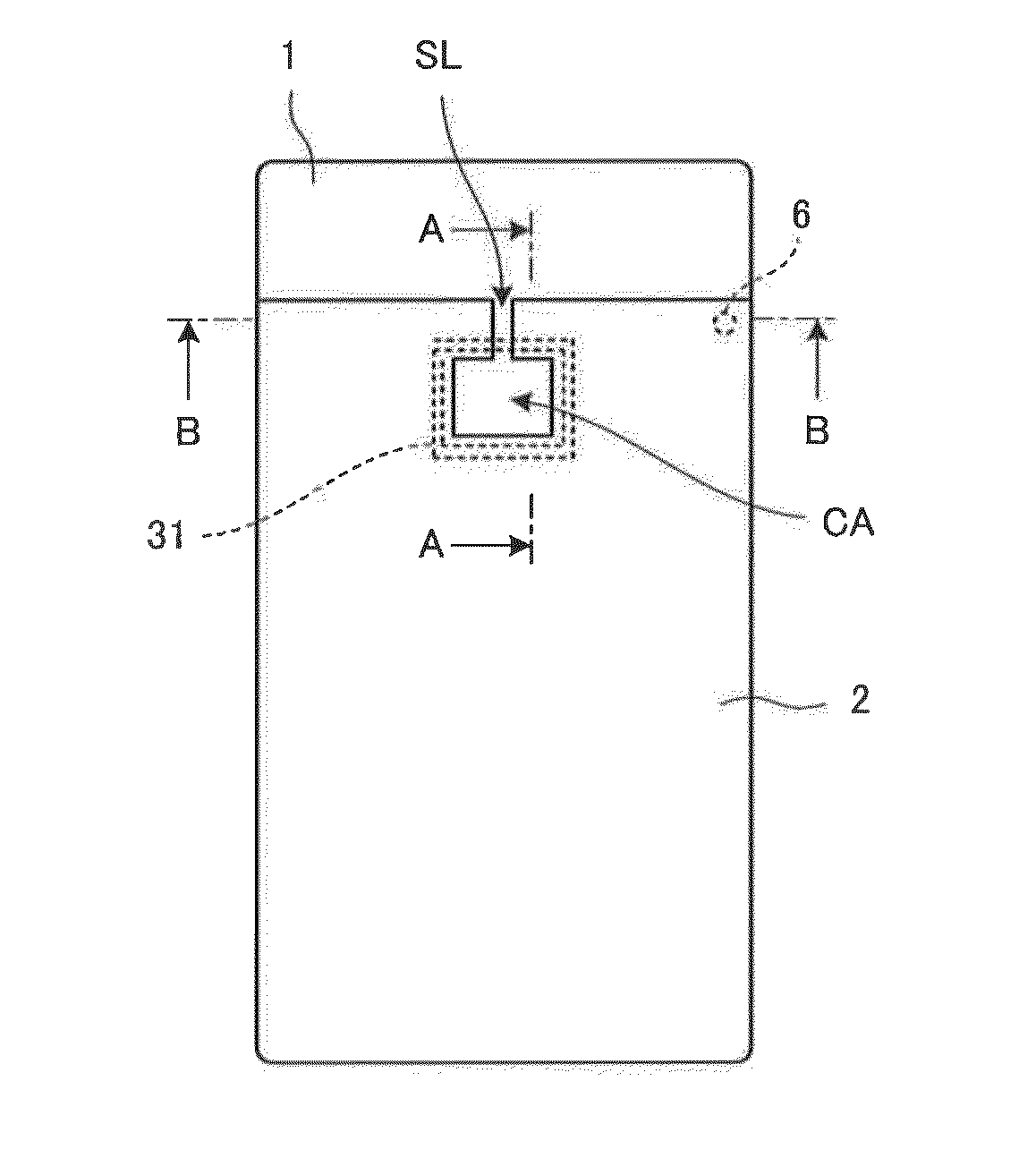
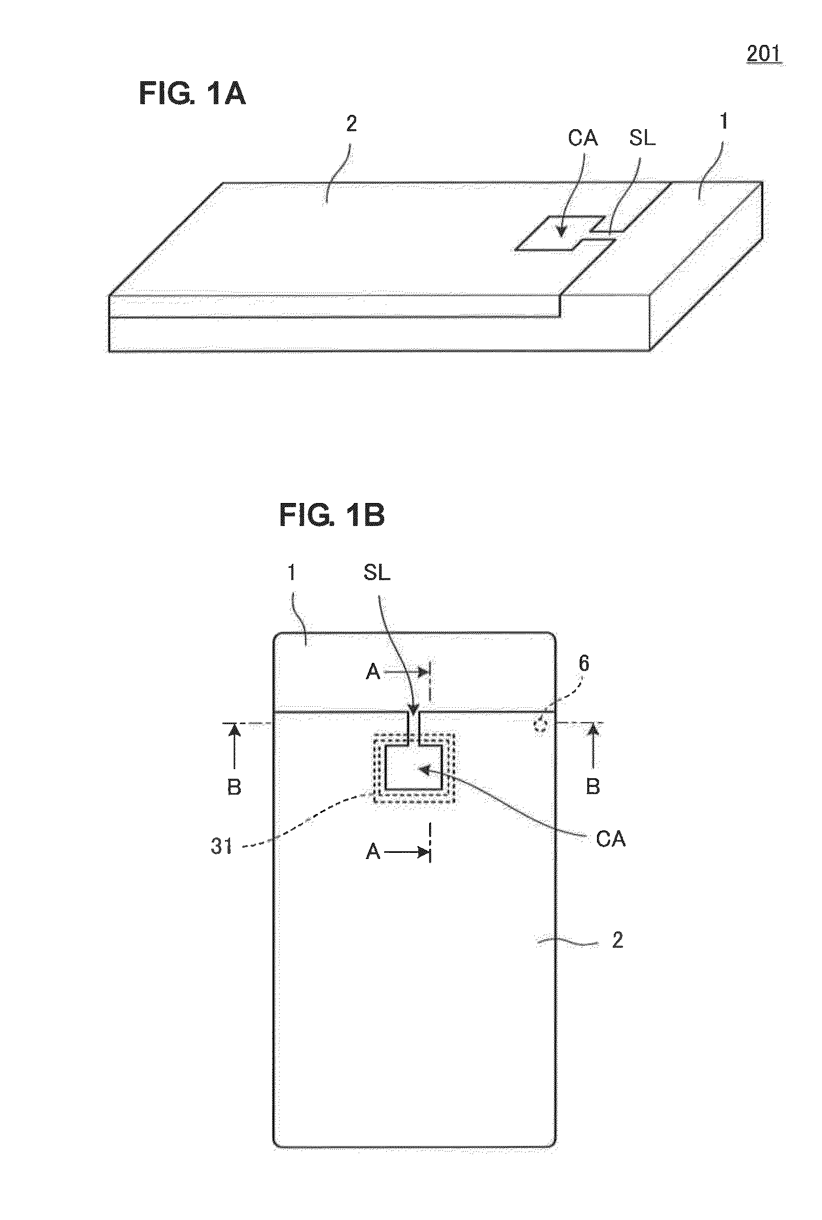
[0049]FIG. 1A is a schematic perspective view of a communication terminal 201 including an antenna apparatus according to the first preferred embodiment when viewed from the back surface of the communication terminal 201. FIG. 1B is a back view of the communication terminal including an antenna apparatus according to the first preferred embodiment. The communication terminal 201 is, for example, a mobile terminal with a camera. The communication terminal 201 includes a casing made of a resin and a metal cover 2. The metal cover 2 includes a conductor aperture CA and a slit SL that connects the conductor aperture CA and an outer edge. The conductor aperture CA is located at a position (offset position) near the outer edge of the metal cover 2. In this examp...

second preferred embodiment

[0074]FIG. 14A is a schematic perspective view of a communication terminal 202 including an antenna apparatus according to the second preferred embodiment of the present invention when viewed from the back surface of the communication terminal 202. FIG. 14B is a back view of the communication terminal including an antenna apparatus according to the second preferred embodiment. The communication terminal 202 includes a metal case 9 that shields a high-frequency circuit formed on the printed circuit board 8 in a casing. The metal case 9 includes the conductor aperture CA and the slit SL that connects the conductor aperture CA and an outer edge. The conductor aperture CA is located at a position (offset position) near the outer edge of the metal case 9. In this example, since the metal case 9 is substantially rectangular in shape, the conductor aperture CA is located at a position near one side of the metal case 9.

[0075]On an inner surface of the metal case 9, the feeding coil module 3...

third preferred embodiment

[0078]In the above-described preferred embodiments, the high current density area preferably is simply specified on the basis of a structure. That is, the first area, which includes the conductor aperture, the slit, and the feeding coil in plan view and is specified by a substantially straight line parallel to a portion of the outer edge of the metal cover connected to the slit, is defined as the high current density area. However, in this case, the constraint may be avoided. For example, the first area illustrated in FIG. 8 may include a portion in which the current density of an induced current is less than approximately 80% (or approximately 50%) of its maximum value. By disposing the ground connection conductor on either side of the slit SL in the first area while avoiding a portion in which the current density of an induced current is in the range from its maximum value to approximately 80% (or approximately 50%), the radiation characteristic of a booster antenna can be maintai...


PUM


Abstract

In an antenna apparatus, on an undersurface of a metal cover, a feeding coil module is disposed. In a casing, a printed circuit board is included. A ground conductor, a feeding pin, and a ground connection conductor are disposed on the printed circuit board. When the metal cover is mounted on the casing, the feeding pin is in contact with a connection portion of the feeding coil module and is electrically connected thereto. The ground connection conductor is in contact with the metal cover and connects the metal cover to the ground conductor. The ground connection conductor is disposed at either side of a slit outside an area in which the current density of an induced current flowing through the metal cover is in a range from a maximum value to approximately 80% of the maximum value or one side of the slit in the area.

Description

BACKGROUND OF THE INVENTION[0001]1. Field of the Invention[0002]The present invention relates to an antenna apparatus preferably for use in short-range communication and a communication terminal including the antenna apparatus.[0003]2. Description of the Related Art[0004]Radio frequency identification (RFID) systems are increasingly becoming popular as product management systems and billing and toll collection management systems. In such an RFID system, a reader / writer and an RFID tag wirelessly communicate with each other to exchange information. Each of the reader / writer and the RFID tag includes an RFID IC chip for processing a signal and an antenna for transmitting and receiving a radio signal. Predetermined information is transmitted between the antennas of the reader / writer and the RFID tag via a magnetic field or an electromagnetic field.[0005]For example, FeliCa (registered trademark) that applies an RFID system to information communication terminals such as mobile telephone...

Claims


Application Information

Patent Timeline
Patent Type & Authority Applications(United States)
IPC IPC(8): H01Q1/48H01Q1/22
CPCH01Q1/2225H01Q1/243H01Q1/48H01Q7/00H01Q13/106H01Q1/22H01Q1/2208H01Q13/10H01Q1/38H01Q7/04
Inventor NAKANO, SHINICHI
Owner MURATA MFG CO LTD
Why Eureka
Try Eureka