One shot injector with dual springs

a dual-spring, injection device technology, applied in the direction of intravenous devices, injection syringes, automatic syringes, etc., can solve the problems of inacceptable device sizes, high force requirements, and large devices, and achieve high viscosity and large force

Active Publication Date: 2012-10-02
SHL MEDICAL AG
View PDF6 Cites 65 Cited by
  • Summary
  • Abstract
  • Description
  • Claims
  • Application Information

AI Technical Summary

Benefits of technology

[0009]The aim of the present invention is to provide an injector being capable of handling the expelling of liquids having high viscosity without increasing the size of the injector in any substantive way.
[0018]The advantages with the present invention are several. Because the device is arranged with at least two spring force means, a large force can be obtained in the device without having to use a very large single spring. The device is thus capable of handling liquid medicament having high viscosity, without the device having to be large and bulky, and thus not very attractive to users.

Problems solved by technology

This type of drugs often have a high viscosity which means that they require high forces in order to press the fluid through a hollow needle when injecting them.
The size of the spring means that the device becomes large, and for some applications and customers, such sizes of the devices are not acceptable.
The idea of having two springs is to handle the rather long travel of the drive member, which could be difficult with a single spring because of a tendency of buckling when fully compressed and becoming entangled with interior components of the device.
This design can be used for handling long travel but cannot be utilised when larger forces are required.
It is not possible to add the forces of the two springs because of the intermediary cup.

Method used


Image

  • One shot injector with dual springs
  • One shot injector with dual springs
  • One shot injector with dual springs

Examples


Embodiment Construction

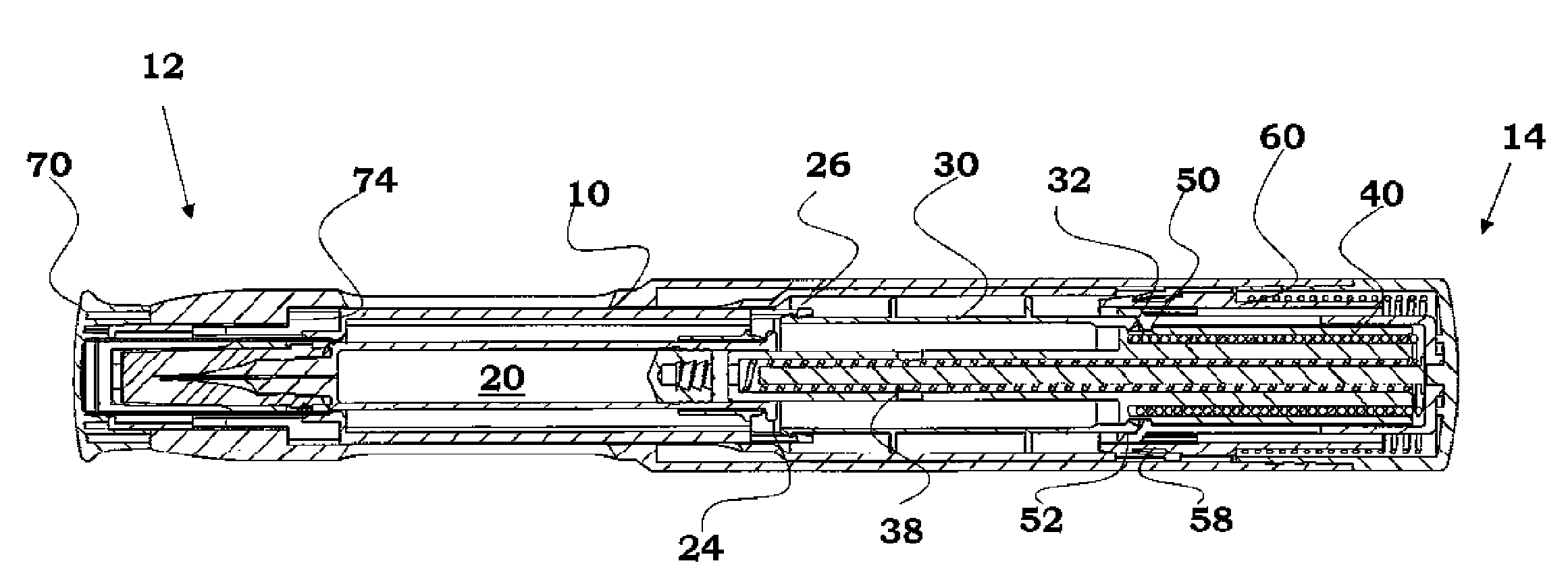
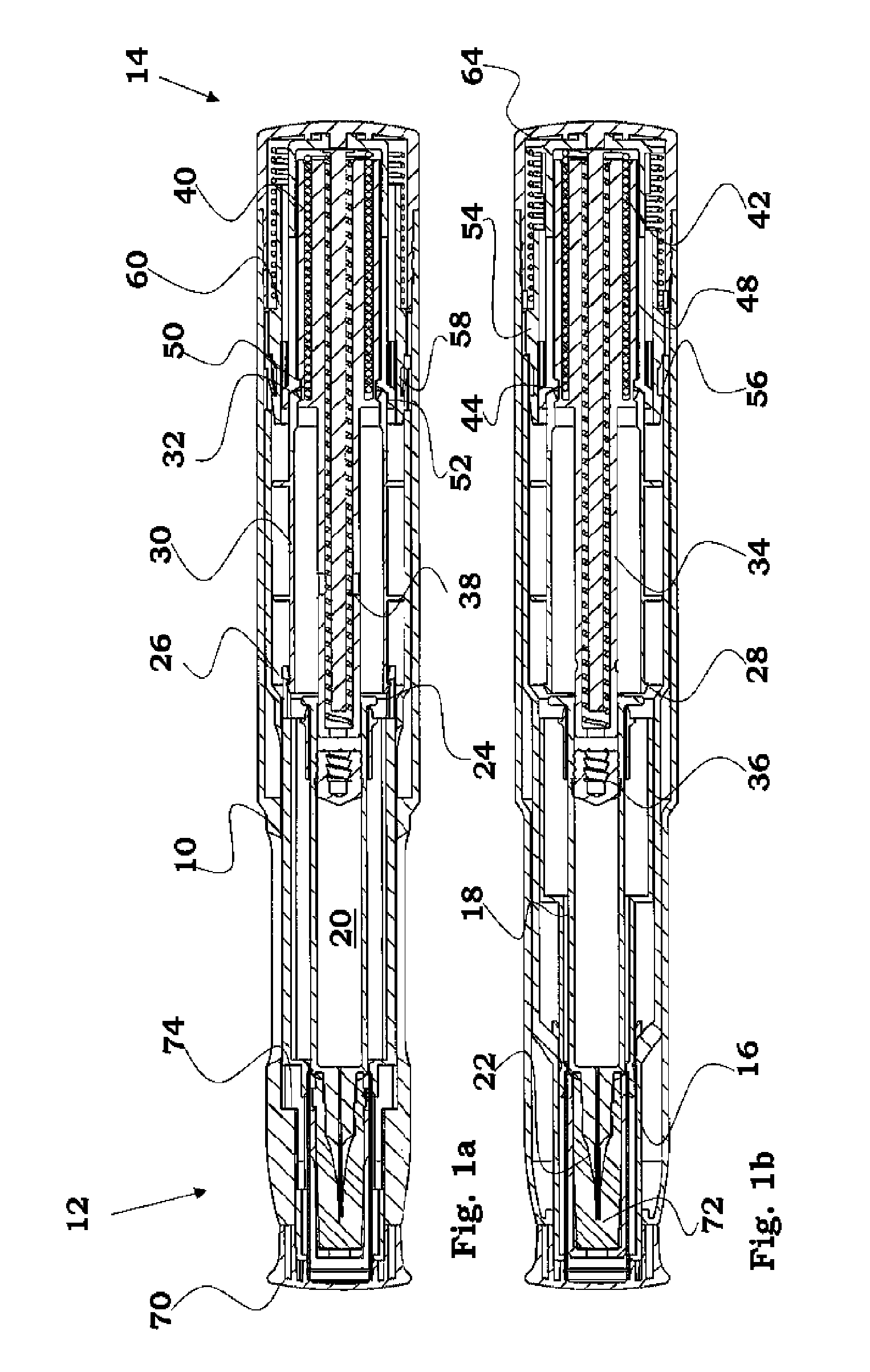
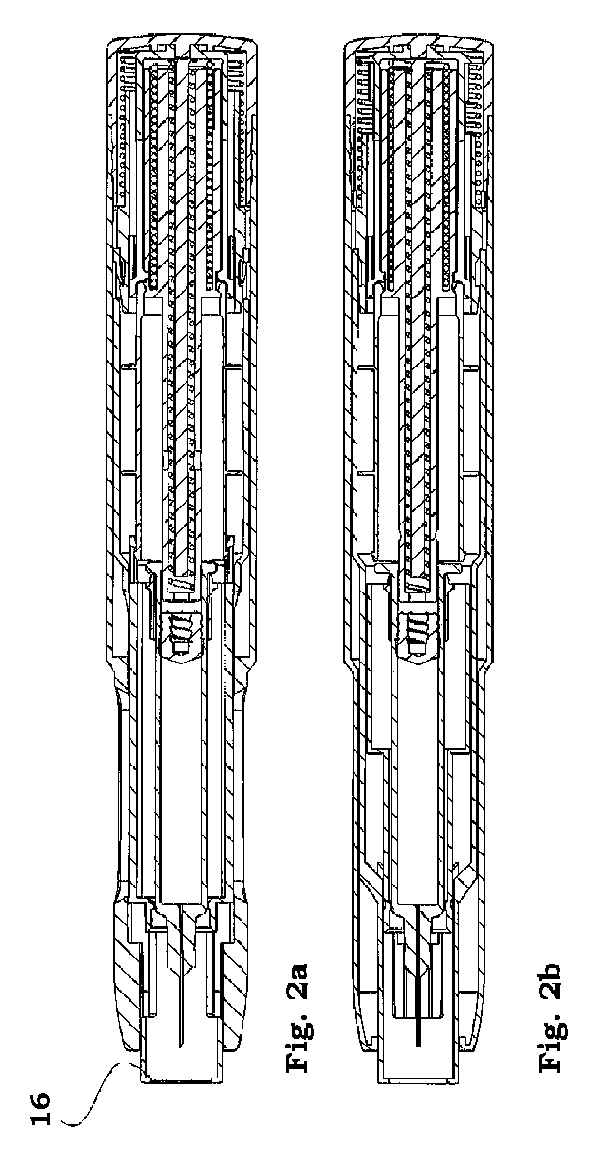
[0029]The embodiment of the injector shown in the drawings comprises an elongated housing 10 with a front end 12, to the left in the figures, which is pressed against the injection site during use, as will be described below, and an opposite rear end 14. At the front end of the housing a generally tubular needle shield 16 is slidably arranged. The rear end of the needle shield extends into the rear part of the housing, in a manner that will be described below.

[0030]Inside the needle shield a medicament container holder 18 is arranged, and inside the container holder a container 20, e.g. a cartridge, a syringe or the like, is arranged containing medicament to be delivered through a needle 22 attached to the container.

[0031]The rear part of the container holder is arranged with tongues 24 having inwardly directed ledges 26. These ledges cooperate with an outwardly directed circumferential ledge 28 of a generally tubular part 30, creating a snap-on fit between these components. At the ...


PUM


Abstract

The present invention relates to a medical delivery device comprising a generally elongated housing, a container containing medicament to be delivered, a drive means capable of acting on said container for expelling said medicament, wherein said drive means comprises at least two force spring means arranged between a fixed part of the device and a movable part of the device.

Description

TECHNICAL FIELD[0001]The present invention relates to an injection device and in particular an injection device capable of handling medicament in fluid form having high viscosity.BACKGROUND ART[0002]The present invention relates to injection devices for injecting medicament and other types of fluids to be used in for example cosmetic treatment.[0003]This type of drugs often have a high viscosity which means that they require high forces in order to press the fluid through a hollow needle when injecting them.[0004]Auto-injectors having an automated injection function often work with spirally wound compression springs, where the springs act on a plunger rod, which in turn acts on a stopper inside a medicament container, for expelling medicament through an attached needle. The other end of the spring is often abutting an inner end surface of the housing of the device, which means that the housing has to be dimensioned to the forces of the spring.[0005]When handling fluids with high vis...

Claims


Application Information

Patent Timeline
Patent Type & Authority Patents(United States)
IPC IPC(8): A61M5/20
CPCA61M5/2033A61M5/3202A61M5/326A61M5/3204A61M2005/2013A61M2005/206A61M2005/31518
Inventor KRONESTEDT, VICTOR
Owner SHL MEDICAL AG
Why Eureka
Try Eureka