Digital potentiometer with independent control over both resistive arms

Active Publication Date: 2012-10-09
ANALOG DEVICES INC
View PDF9 Cites 2 Cited by
  • Summary
  • Abstract
  • Description
  • Claims
  • Application Information

AI Technical Summary

Problems solved by technology

The problem with traditional digital potentiometers is that the resistance between terminal A and the wiper (one of the resistance “arms”) is dependant on the resistance between terminal B and the wiper (the other resistance “arm”).

Method used


Image

  • Digital potentiometer with independent control over both resistive arms
  • Digital potentiometer with independent control over both resistive arms
  • Digital potentiometer with independent control over both resistive arms

Examples


Embodiment Construction

[0017]The subject invention will now be described in detail for specific preferred embodiments of the invention, it being understood that these embodiments are intended only as illustrative examples and the invention is not to be limited thereto.

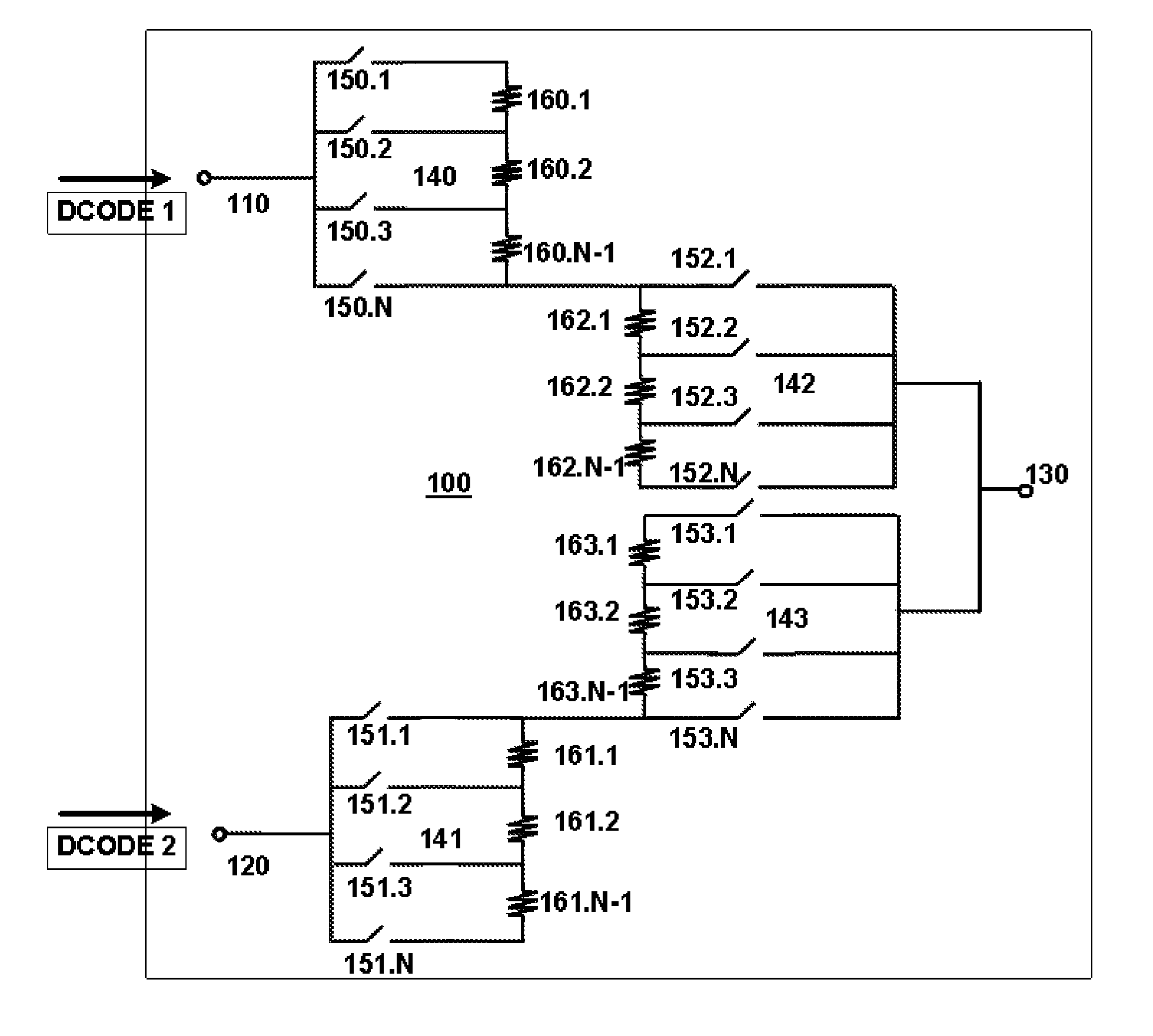
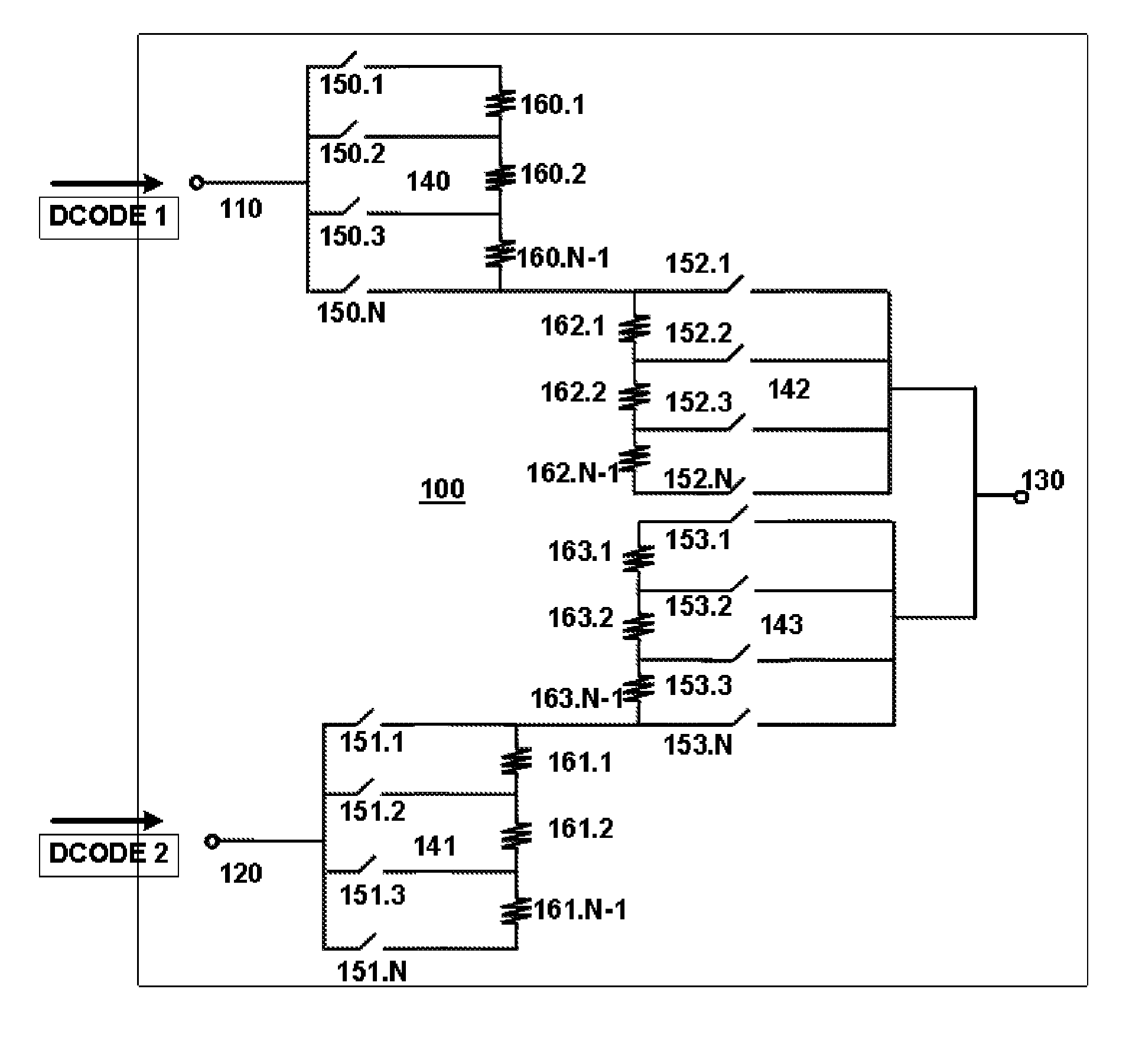
[0018]A dependence on the resistance between another resistance branch to modify the resistance between a terminal and the wiper may be overcome by applying separate digital input signals to each one of the primary terminals of the digital potentiometer. Embodiments of the present invention may provide a circuit which includes a plurality of string arrays each having a plurality of parallel field-effect transistors that may operate as switches. Resistive arrays that are connected in series may be coupled to the terminals of the plurality of switches as further exemplified in the example embodiments.

[0019]FIG. 1 illustrates a digital potentiometer 100 according to the present invention. Digital potentiometer 100 may include two primary termin...


PUM


Abstract

A digital potentiometer includes a circuit containing multiple string arrays, each having a plurality of switching devices connected to an array of resistors. Each input terminal receives a separate digital input code enabling the resistance of one of the arms to be varied without changing the other.

Description

FIELD OF THE INVENTION[0001]The present invention relates to the architecture of a digital potentiometer which allows for an independent control of the resistance of the potentiometer arms in the potentiometer. The present invention further relates to the input of multiple digital codes to a digital potentiometer to change the resistances of each of the potentiometer arms in the potentiometer.BACKGROUND INFORMATION[0002]The following application is hereby incorporated by reference herein: U.S. patent application Ser. No. 12 / 367,243 (“the '243 application”), filed Feb. 6, 2009.[0003]Potentiometers are electric devices used in a variety of electrical circuits, including those where a specific voltage output is needed. Potentiometers allow for a user to create a constant resistance between the terminals, whereupon the user can change the resistance between the terminals by mechanically adjusting the potentiometer. In a digital potentiometer, a digital input code is input to the potenti...

Claims


Application Information

Patent Timeline
Patent Type & Authority Patents(United States)
IPC IPC(8): H01C10/30
CPCH01C10/30
Inventor JHA, KAUSHAL KUMAR
Owner ANALOG DEVICES INC
Why Eureka
Try Eureka