Digital potentiometer with resistor binary weighting decoding

a digital potentiometer and resistor technology, applied in the field of digital potentiometers, can solve the problem of relativly large number of components needed to implement the digital potentiometer

Active Publication Date: 2005-12-08
SEMICON COMPONENTS IND LLC
View PDF17 Cites 14 Cited by
  • Summary
  • Abstract
  • Description
  • Claims
  • Application Information

AI Technical Summary

Benefits of technology

[0010] The present invention includes digital potentiometers that may be implemented using significantly fewer components than are used in the conventional digital potentiometer 100 of FIG. 1, while providing the same resolution, i.e., same number of wiper positions.

Problems solved by technology

One disadvantage of this configuration is the relatively large number of components necessary to implement the digital potentiometer, including the 2n−1 resistors of string 101, the 2n wiper switches, and the many components of logic decoder 108.

Method used


Image

  • Digital potentiometer with resistor binary weighting decoding
  • Digital potentiometer with resistor binary weighting decoding
  • Digital potentiometer with resistor binary weighting decoding

Examples


example 1

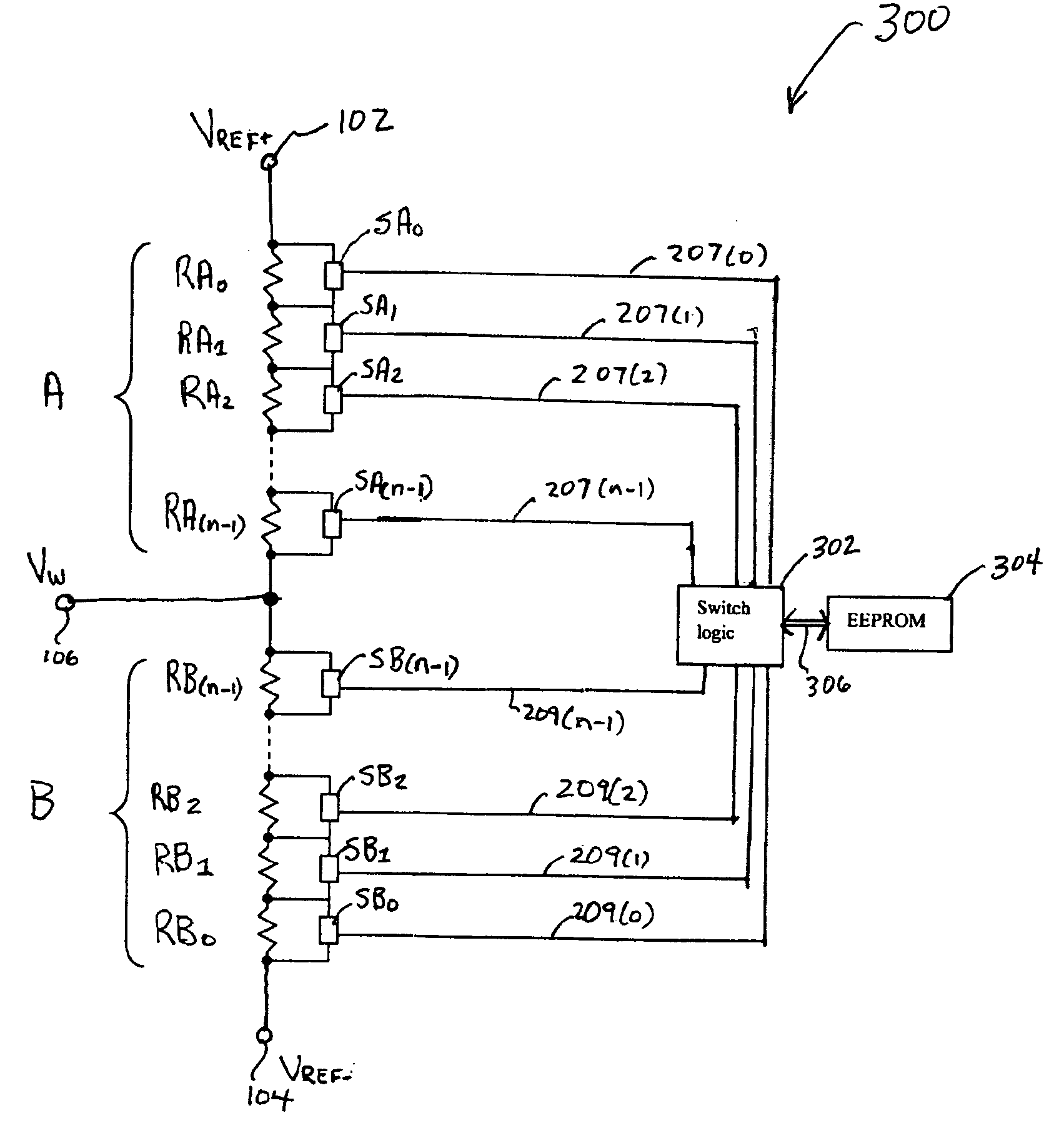
[0047] Assume that the digital potentiometer 200 has a four bit (i.e., n=4) wiper address, and accordingly has 24, i.e., 16, wiper positions. In such an instance, string 201 of digital potentiometer 200 will include a total of eight resistors in series, with four resistors RA0-RA3 in first set A and four resistors RB0-RB3 in second set B of string 201. The mirror image first resistors RA0 and RB0, which are coupled to terminals 104 and 102, respectively, have a same resistance of 20*R0, i.e., R0. The mirror image second resistors RA1 and RB1 have a resistance of 21*R0, i.e., 2*R0. Mirror image third resistors RA2 and RB2 have a resistance of 22*R0, i.e., 4*R0. Finally, the mirror image fourth resistors RA3 and RB3, which are both coupled to node 205, have a same resistance of 23*R0, i.e., 8*R0. In such a configuration, the total resistance of each of first set A and second set B of string 201 is 2n−1*R0, i.e., 15*R0. Moreover, the digital potentiometer 200 will have a total of eight...

example 2

[0076] Assume that the digital potentiometer 400 has an eight bit (i.e., n=8) wiper address, and accordingly has 28, i.e., 256, wiper positions. As mentioned, the value of m may be selected in cases where n≧4, provided that m≧2, in order to optimize the number of resistors and switches of the digital potentiometer 400 for a particular application. For this example, assume that m=4, so that p=4, i.e., n−m=4. In such a case, string 401 will include a total of 23 resistors in series, with four resistors RA0-RA3 in first set A, four resistors RB0-RB3 in second set B, and fifteen resistors RC0-RC14 in third set C.

[0077] Within the first and second sets A and B of string 401, the mirror image first resistors RA0 and RB0, which are coupled to terminals 104 and 102, respectively, have a same resistance of 20*R0, i.e., R0. The mirror image second resistors RA1 and RB1 have a resistance of 21*R0, i.e., 2R0. The mirror image third resistors RA2 and RB2 have a resistance of 22*R0, i.e., 4*R0. ...

example 3

[0084] Assume that another version digital potentiometer 400 has an eight bit (i.e., n=8) wiper address, and accordingly has 28, i.e., 256, wiper positions. As mentioned, the value of m may be selected in cases where n≧4, provided that n≧3>m≧2, in order to optimize the number of resistors and switches of the digital potentiometer 400 for a particular application. For this Example 3, assume that m=5, so that p=3, i.e., n−m=3. In such a case, string 401 will include a total of 17 resistors, with five resistors RA0-RA4 in first set A, five resistors RB0-RB4 in second set B, and seven resistors RC0-RC6 in third set C. The sequential resistors RA0-RA4 and RB0-RB4 will have values of 20*R0, 21*R0, 22*R0, 23*R0, and 24*R0, i.e., R0, 2R0, 4R0, 8R0, and 16R0, respectively. Moreover, each of the seven resistors RC0-RC6 will have a value of R0 / (23−1) i.e., R0 / 7.

[0085] In addition, the digital potentiometer 400 will have 18 switches, including five switches SA0-SA4, five switches SB0-SB4, and ...


PUM


Abstract

A digital potentiometer includes a string of impedance units in series. The string includes identical first and second sets of impedance units whose individual impedance values increment by a power of two. One of a plurality of switches is coupled in parallel with each respective impedance unit. The switches that are coupled to the first set of impedance units receive logical control signals complementary to logical control signals received by the respective switches coupled to the second set of impedance units, so that for every impedance unit of the first set that is bypassed (not bypassed), the identical impedance unit of the second set is not bypassed (bypassed). The string may include only the first and second sets of impedance units, or may include at least one third impedance unit in series with the first and second sets in a multi-stage design.

Description

BACKGROUND [0001] a. Technical Field [0002] The present invention is in the field of digital potentiometers. [0003] b. Discussion of the Related Art [0004] Digital potentiometers are electronic circuits that can provide a variable impedance as a result of processing a digital sequence. A digital potentiometer has a fixed-value impedance connected between two reference voltage terminals. This impedance is provided by a string of impedance units that can be selectively connected to a third terminal, called the wiper terminal herein, through electronic switches controlled by digital signals. Digital potentiometers can be used in digital to analog converters, and as replacements for mechanical potentiometers and rheostats. [0005] The fineness of adjustment, resolution, or “granularity” of a digital potentiometer is typically determined by the number of digital bits used for the selection of the desired wiper position. For instance, a three-bit wiper address (n=3) allows for 23 (i.e., 8)...

Claims


Application Information

Patent Timeline
Patent Type & Authority Applications(United States)
IPC IPC(8): G01R1/20G01R27/08H03H7/24
CPCH03H7/24G01R1/203
Inventor IACOB, RADU H.GEORGESCU, SORIN S.WOJSLAW, CHARLES FRANKWOJSLAW, TONI M.
Owner SEMICON COMPONENTS IND LLC
Why Eureka
Try Eureka