Quick-response constant current source parallel system and implementation method thereof

A fast-response, constant-current source technology, applied in the field of constant-current sources, can solve the problems of high cost, difficult system stability, and high requirements, and achieve the effects of cost saving, simple implementation, and constant output current.

Active Publication Date: 2010-10-06
ZTE CORP
View PDF4 Cites 12 Cited by
  • Summary
  • Abstract
  • Description
  • Claims
  • Application Information

AI Technical Summary

Problems solved by technology

The main problems of this digital control scheme are: 1. The requirements for DSP are high, and high-performance DSP chips are needed to realize it, which is costly; 2. The control algorithm is com

Method used


Image

  • Quick-response constant current source parallel system and implementation method thereof
  • Quick-response constant current source parallel system and implementation method thereof
  • Quick-response constant current source parallel system and implementation method thereof

Examples


Embodiment 1

[0042] The constant current source current value setting unit sets a constant current source system with a system output of 500A. The number of constant current source modules in the constant current source parallel unit is 5, and the output current of each constant current source module is 100A.

[0043] The formula for establishing the data table in the MCU data processing unit is:

[0044] v = k X ni n - m + a - - - ( 1 )

[0045] Among them, v represents the output voltage of the system, n represents the total number of constant current source modules of the constant current source parallel unit, i represents the output current of each constant current source module, and m represents the module that exits the system due to a fault in the constant current source parallel unit. The values ​​of quantity, k and a are selected according to actual applications, where k=0.02 and a=0.5.

[0046] When the five constant current source modules in t...

Embodiment 2

[0049] The constant current source current value setting unit sets the constant current source system with an output of 800A. The number of constant current source modules in the constant current source parallel unit is 10, and the output current of each constant current source module is 80A.

[0050] According to the actual application, the value k=0.04 and a=0.8, then the formula for establishing the data table in the MCU data processing unit is:

[0051] v = 0.04 X ni n - m + 0.8 - - - ( 2 )

[0052] Among them, v represents the output voltage of the system, n represents the total number of constant current source modules of the constant current source parallel unit, i represents the output current of each constant current source module, and m represents the module that exits the system due to a fault in the constant current source parallel unit. Quantity.

[0053] If all 10 constant current source modules work normally, the output voltag...


PUM


Abstract

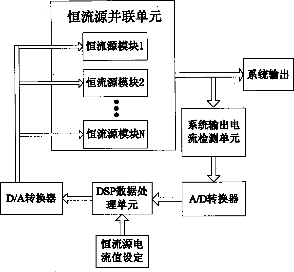
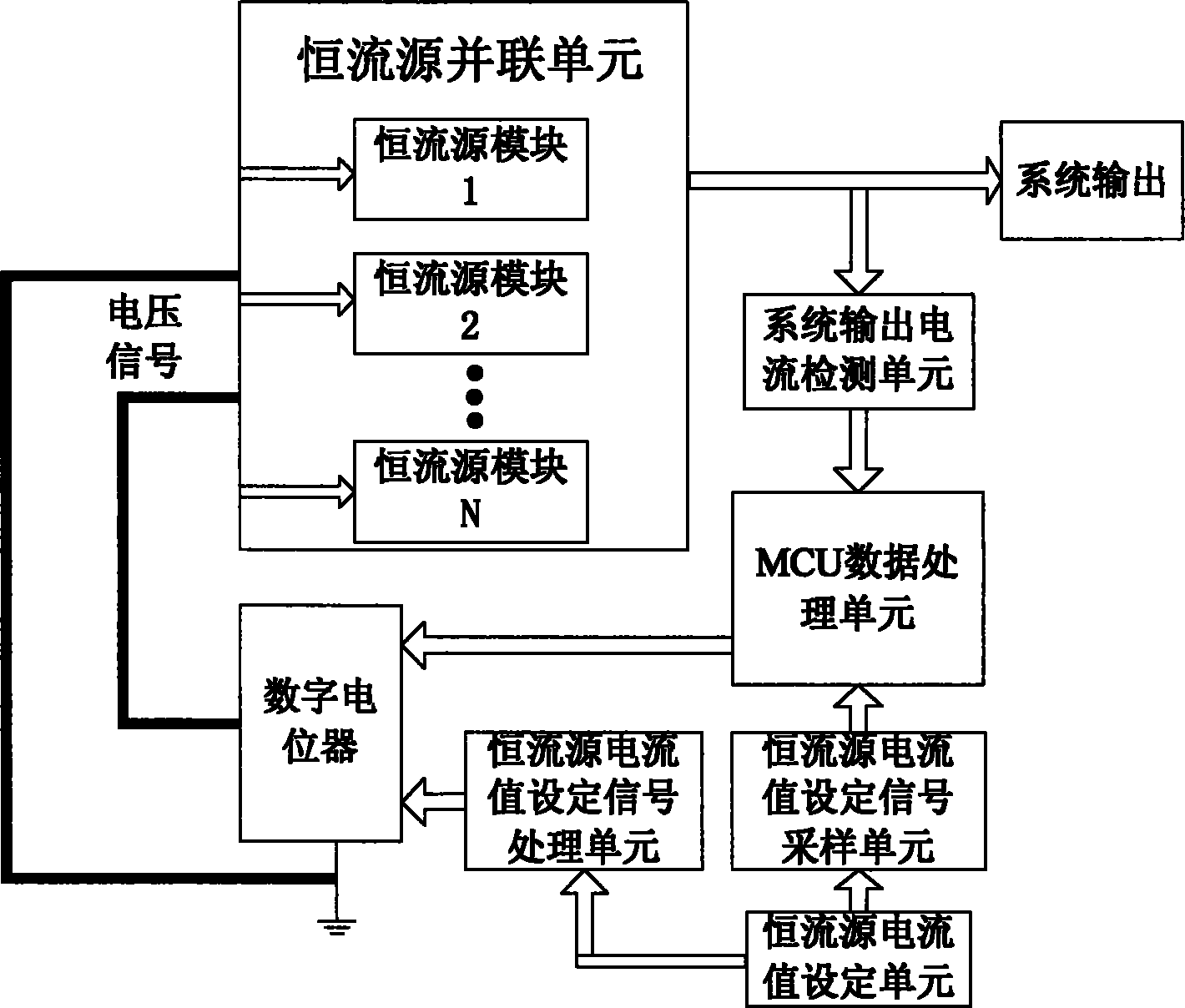
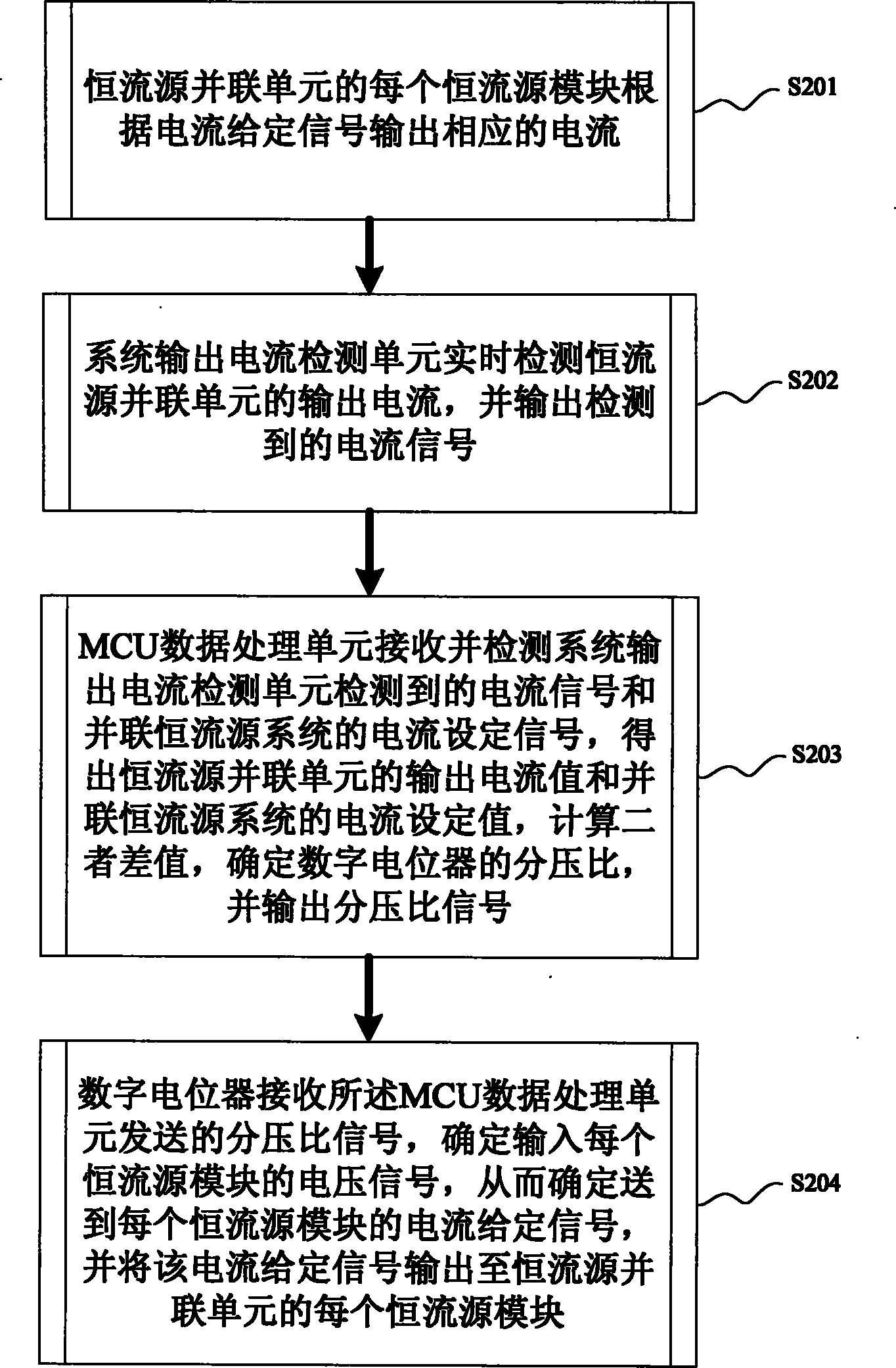
The invention discloses a quick-response constant current source parallel system and an implementation method thereof. The system comprises a constant current source parallel unit, a system output current detection unit, an MCU data processing unit and a digital potentiometer, wherein the constant current source parallel unit consists of a plurality of constant current source modules which are connected in parallel; each module outputs a corresponding current according to a given current signal; the system output current detection unit detects the output current of the constant current source parallel unit in real time to output a detected current signal; the MCU data processing unit receives and detects the current signal detected by the system output current detection unit and a given system current signal to output a voltage division ratio signal; and the digital potentiometer receives the voltage division ratio signal transmitted by the MCU data processing unit to determine and output the given current signal of each constant current source module. Quick adjustment for variation in output current can be realized by a simple implementation method without complex control software when single or more modules are failed; and the cost can be saved and constant output current of the system can be ensured.

Description

Technical field [0001] The invention relates to a constant current source technology, in particular to a low-cost, fast response constant current source parallel system and an implementation method thereof. Background technique [0002] The constant current source is a power supply device that provides a constant current to the load. Its characteristic is to keep the output current constant when the external power grid fluctuates and the load impedance changes. With the development of power electronics and semiconductor devices, the demand for the output power of constant current sources is also increasing. In many cases, the output voltage is up to several hundred volts and the output current is up to several hundred amperes or even thousands of amperes. The development of capacity, high voltage, high power and high reliability is the inevitable trend of constant current source. [0003] Due to device limitations, the output power of a single constant current source can generally...

Claims


Application Information

Patent Timeline
IPC IPC(8): G05F1/10
Inventor 郭宇操敏
Owner ZTE CORP
Why Eureka
Try Eureka