Rotary transformer decoding circuit and control method thereof

A resolver and resolver decoding technology, which is applied to transformers, circuits, inductors, etc., can solve the problems of increasing research and development and production and processing costs, and achieve the effect of self-adaptive matching

Inactive Publication Date: 2015-08-05
INVT ELECTRIC VEHICLE DRIVE TECH SHENZHEN CO LTD
View PDF6 Cites 12 Cited by
  • Summary
  • Abstract
  • Description
  • Claims
  • Application Information

AI Technical Summary

Problems solved by technology

At present, the resolver decoding circuit can only match the circuit for a specific resolver. Since the range of the excitation signal of the resolver and the feedback sine and cosine signals are fixed, it is necessary to recalculate the resolution of the resolver circuit for different resolvers. parameters, change the PCB for circuit matching
At present, there are various resolvers for motors in the field of electric vehicles and industrial control. In order to match the resolver, the control board of the motor controller needs to be repeatedly designed or processed, which increases the cost of R&D and production processing.

Method used


Image

  • Rotary transformer decoding circuit and control method thereof
  • Rotary transformer decoding circuit and control method thereof
  • Rotary transformer decoding circuit and control method thereof

Examples


Embodiment Construction

[0055] The following will clearly and completely describe the technical solutions in the embodiments of the present invention with reference to the accompanying drawings in the embodiments of the present invention. Obviously, the described embodiments are only some, not all, embodiments of the present invention. Based on the embodiments of the present invention, all other embodiments obtained by persons of ordinary skill in the art without making creative efforts belong to the protection scope of the present invention.

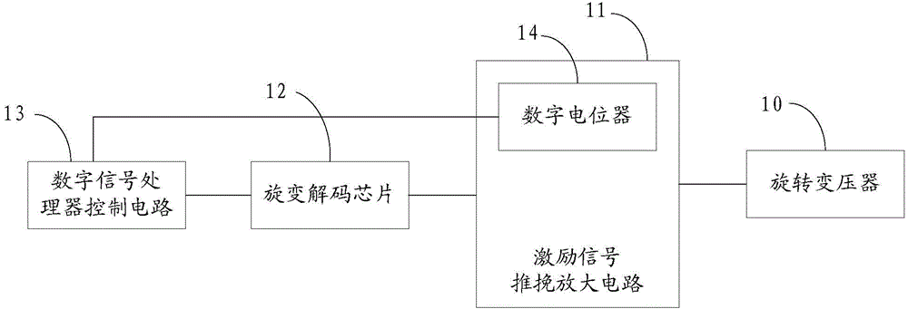
[0056] Such as figure 1 As shown, it is a resolver decoding circuit disclosed in an embodiment of the present invention, including: an excitation signal push-pull amplifier circuit 11, a resolver decoding chip 12 and a digital signal processor control circuit 13; wherein:

[0057] The resolver decoding chip 12 outputs a preset excitation signal, and inputs the preset excitation signal to the input end of the excitation signal push-pull amplifier circuit 11 con...


PUM


Abstract

The invention discloses a rotary transformer decoding circuit. A rotary transformer decoding chip outputs a preset excitation signal, and inputs the preset excitation signal to the input end of an excitation signal push-pull amplifier circuit connected with the rotary transformer decoding chip. The excitation signal push-pull amplifier circuit receives the preset excitation signal and amplifies the preset excitation signal. The excitation signal push-pull amplifier circuit outputs an excitation signal needed for a rotary transformer according to the resistance of a digital potentiometer. A digital signal processor control circuit is connected with the rotary transformer decoding chip, receives a feedback signal of the rotary transformer decoding chip, and adjusts the resistance of the digital potentiometer connected with the digital signal processor control circuit, thus realizing adaptive matching for different rotary transformers. The invention further discloses a control method of the rotary transformer decoding circuit.

Description

technical field [0001] The invention relates to the technical field of rotary transformers, in particular to a rotary transformer decoding circuit and a control method thereof. Background technique [0002] A resolver is an electromagnetic sensor, also known as a synchronous resolver. It is a small AC motor for measuring angles, used to measure the angular displacement and angular velocity of the rotating object, and consists of a stator and a rotor. Among them, the stator winding is used as the primary side of the transformer to receive the excitation voltage. The rotor winding is used as the secondary side of the transformer, and the induced voltage is obtained through electromagnetic coupling. Resolver, referred to as resolver, is a signal component whose output voltage changes with the rotor angle. [0003] The resolver is installed on the motor, and the resolver decoding circuit is used to analyze the motor speed and angle signals fed back by the resolver. At presen...

Claims


Application Information

Patent Timeline
Patent Type & Authority Applications(China)
IPC IPC(8): G01D5/12H01F38/18
Inventor 李汉平
Owner INVT ELECTRIC VEHICLE DRIVE TECH SHENZHEN CO LTD
Why Eureka
Try Eureka