
An Array Beamforming Method Based on Pattern Reconstruction Unit

A technology of pattern reconstruction and pattern, which is applied in the field of electromagnetic waves, can solve the problem that there is no optimal selection method for pattern patterns

Active Publication Date: 2021-04-30
UNIV OF ELECTRONICS SCI & TECH OF CHINA
View PDF5 Cites 0 Cited by
  • Summary
  • Abstract
  • Description
  • Claims
  • Application Information

AI Technical Summary

Problems solved by technology

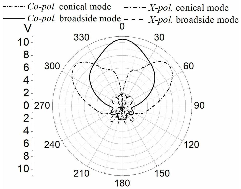
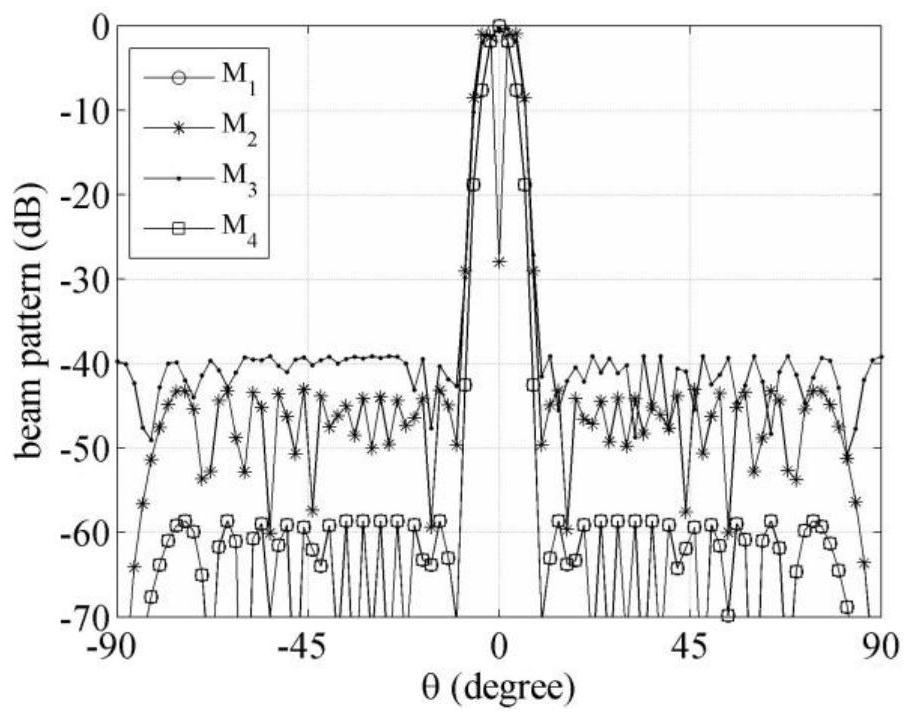
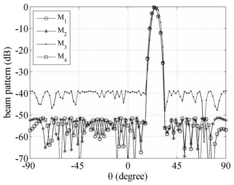
At present, the selection of different pattern modes of array elements is mainly done by experience. Usually, all array elements choose the same pattern pattern, and there is no better pattern pattern optimization method to assist in pattern optimization.

Method used


Image

  • An Array Beamforming Method Based on Pattern Reconstruction Unit
  • An Array Beamforming Method Based on Pattern Reconstruction Unit
  • An Array Beamforming Method Based on Pattern Reconstruction Unit

Examples


Embodiment Construction

[0021] Taking the line array antenna as an example, the theoretical process of the planar array antenna can be deduced by analogy. Assuming that the antenna has N array elements with K different pattern patterns (uniform or non-uniform) with arbitrary distribution characteristics, then when the array antenna receives signals, the combined electric field strength of the array antenna can be described as:

[0022]

[0023] where w n 、a n (θ) and E n,k (θ) are respectively the complex weight coefficient of the nth array element factor, the array factor and the far-field electric field strength corresponding to the kth pattern pattern, and the azimuth angle θ∈[0°, 180°].

[0024] Vectorize the above formula to get:

[0025] f(θ)=e a (θ)w (0)

[0026] Among them, the array weight coefficient vector composed of N array element weight coefficients e a (θ)=a(θ)⊙e N,K (θ), a(θ)=[a 1 (θ) … a n (θ) … a N (θ)] H , e a (θ) is the product of the array factor of N array el...


PUM


Abstract

The present invention provides an array beamforming method based on a pattern reconstruction unit, 1) an initialization step; 2) an iterative step: first, solve a convex optimization problem by traversing all different patterns of pattern combinations, and then take The combination of pattern patterns when the minimum sidelobe level is the smallest is used as the optimal combination of pattern patterns, and the combination of optimal pattern patterns and corresponding optimal array weight coefficients are output. The present invention realizes the adaptive matching between the pattern of the pattern and the pointing of the array beam through the optimized selection of the pattern pattern of the array unit and the optimized design of the array weight coefficient, lowers the side lobe level of the array antenna, and improves the performance of the array antenna. gain.

Description

technical field [0001] The invention relates to electromagnetic wave technology, in particular to array beam forming technology. Background technique [0002] With its flexible beam scanning capability, array antennas are widely used in many fields related to national economy and people's livelihood, such as radar, communication, navigation, and remote sensing. In order to transmit or receive signals in different directions, the array antenna is generally required to have a wide-angle scanning capability. In order to realize this function, the industry proposes a radiation pattern reconfigurable antenna, which is an antenna capable of reconfiguring the radiation pattern while keeping the antenna frequency and polarization characteristics unchanged. Since the current distribution on the antenna radiating structure directly determines the characteristics of the antenna radiation pattern, selecting the various current distributions required and the method of switching between ...

Claims


Application Information

Patent Timeline
Patent Type & Authority Patents(China)
IPC IPC(8): H01Q3/28
CPCH01Q3/28
Inventor 雷世文田径胡皓全丁孝翔林志鹏陈波杨伟唐璞何子远邱翔东
Owner UNIV OF ELECTRONICS SCI & TECH OF CHINA
Learn More