Magnetic head slider

a slider and head technology, applied in the field of magnetic head sliders, can solve problems such as uniform magnetization, and achieve the effect of reducing the influence of the induction field of the heater coil

Inactive Publication Date: 2012-10-09
HITACHI GLOBAL STORAGE TECH NETHERLANDS BV
View PDF22 Cites 30 Cited by
  • Summary
  • Abstract
  • Description
  • Claims
  • Application Information

AI Technical Summary

Problems solved by technology

However, as noted above, if the induction field by in the ABS direction Y generated by the electric current i flowing in the heater coil 410 extends into the lower magnetic field 210, the magnetizing direction of the lower magnetic field rotates partially and an area is created wherein the magnetization is not uniform.

Method used


Image

  • Magnetic head slider
  • Magnetic head slider
  • Magnetic head slider

Examples


first embodiment

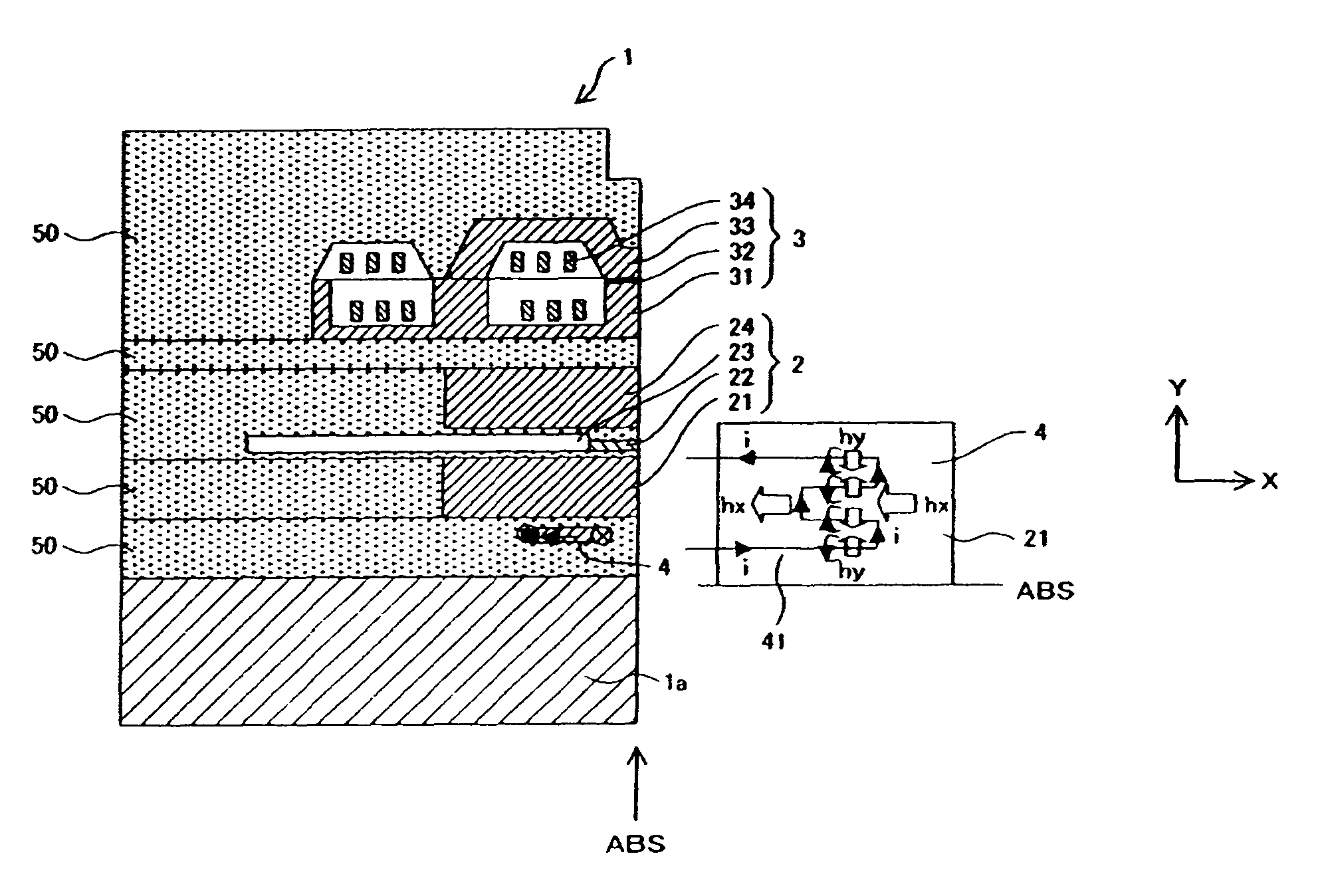
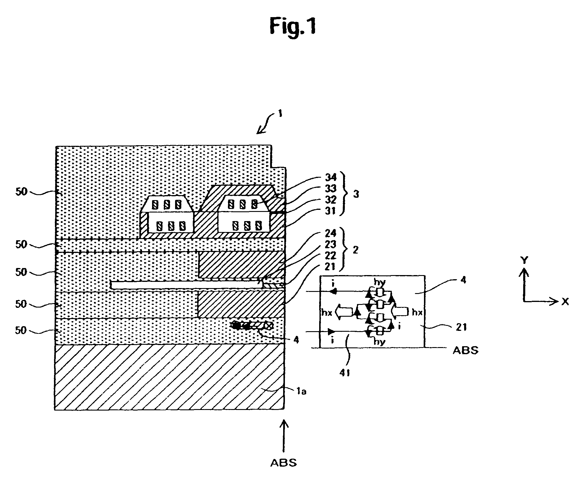
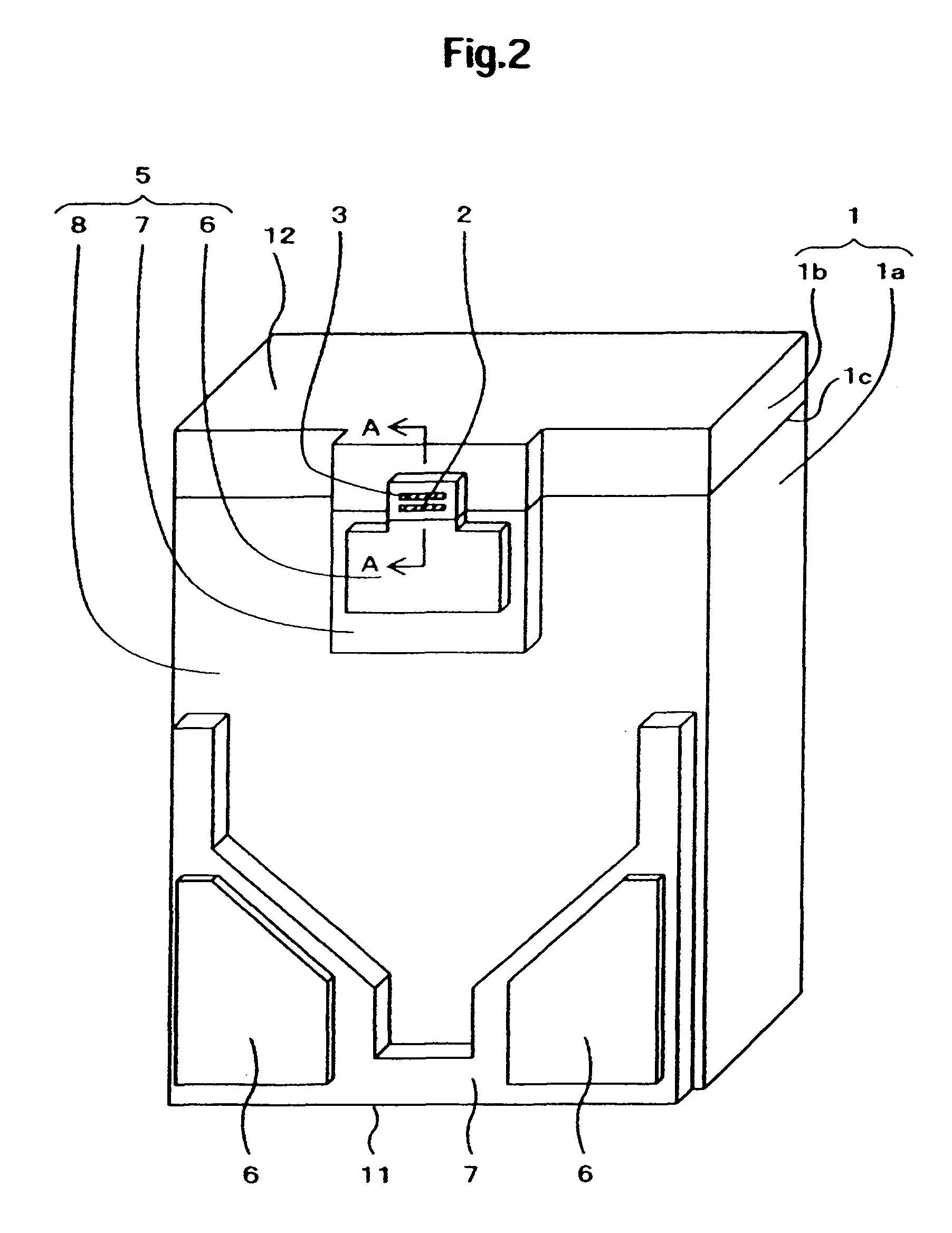
[0029]FIG. 1 is a sectional view taken on line A-A in FIG. 2, showing the vicinity of a trailing end face 12 of a magnetic head slider 1 according to the present invention. A thin film head portion 1b formed on an element forming surface 1c of an Altic substrate 1a of the magnetic head slider 1 includes a heater 4, a read element 2, a write element 3, insulating layers 50 such as alumina layers for isolating them, and electric wiring films (not shown) for those elements. The read element 2 is made up of a lower magnetic shield 21, a magnetoresistive film 22, an electrode 23 and an upper magnetic shield 24. An insulating layer (gap layer) is disposed between the lower magnetic shield 21 and the magnetoresistive film 22 and a like layer is disposed between the magnetoresistive film 22 and the upper magnetic shield 23. The magnetoresistive film 22 is a GMR (Giant Magnetoresistive) film or a TMR (Tunneling Magnetoresistive) film. The write element 3 is made up of a lower magnetic pole p...

third embodiment

[0037]FIG. 6 shows the relation between the distance from the heater coil 41 disposed behind the lower magnetic shield 21 and the strength of the induction field hy generated upon energization of the heater coil 41. When an electric current of 10 mA is supplied to the heater coil 41, a magnetic field generated at a position spaced about 0.1 μm (1×10⁻⁷ μm) from the heater coil 41 is about 200 Oe (16 kA / m). It is seen that this magnetic field can be made 50 Oe (4 KA / m) or less by setting the distance at about 0.4 μm (4×10⁻⁷ μm) or more. Thus, in the above third embodiment, from the relation with the amount of the electric current supplied, the distance between the lower magnetic shield 21 and the heater coil 41 disposed behind the lower magnetic shield may be set at a distance at which the induction field hy becomes 50 Oe (4 kA / m) or less.

[0038]According to the above third embodiment, since the induction fields hy and hx inducted upon energization of the heater coil 41 do not exert an...


PUM

PropertyMeasurementUnit
flying heightaaaaaaaaaa
thicknessaaaaaaaaaa
widthaaaaaaaaaa

Abstract

Embodiments of the present invention help to provide a flying height adjusting type magnetic head slider with reduced influence of a heater coil induction field. According to one embodiment, a magnetic head slider comprises a heater, a read element, and a write element, which are formed on a substrate. The heater is formed between a lower magnetic shield of the read element and the substrate by meandering a heater coil in direction Y going away from ABS. Magnetic fields by generated in direction Y orthogonal to a track width direction X of the lower magnetic field upon energization of the heater coil are offset each other, exerting no influence on the magnetized state in the track width direction X of the lower magnetic shield. A magnetic field hx induced in the track width direction X of the lower magnetic shield is coincident with the magnetizing direction of the lower magnetic shield, acting to maintain the magnetized state of the lower magnetic shield.

Description

CROSS-REFERENCE TO RELATED APPLICATION[0001]The instant nonprovisional patent application claims priority to Japanese Patent Application No. 2006-336184 filed Dec. 13, 2006 and which is incorporated by reference in its entirety herein for all purposes.BACKGROUND OF THE INVENTION[0002]A magnetic disk drive has a rotatable magnetic disk, a magnetic head slider supported by a suspension and carrying read / write elements thereon, and a positioning mechanism for moving and positioning the magnetic head slider in a radial direction of the magnetic disk through the suspension, the magnetic head slider being adapted to travel over the magnetic disk relatively to read and write information with respect to the magnetic disk. The magnetic head slider flies stably over the magnetic disk through an air bearing. In order to attain a high recording density of the magnetic disk drive and a consequent larger capacity of the magnetic disk drive, it is necessary to shorten the distance between the magn...

Claims


Application Information

Patent Timeline
Patent Type & Authority Patents(United States)
IPC IPC(8): G11B5/60G11B5/127
CPCG11B5/3133G11B5/6005G11B5/6064G11B5/3967G11B5/607
Inventor OHTSU, TAKAYOSHI
Owner HITACHI GLOBAL STORAGE TECH NETHERLANDS BV
Why Eureka
Try Eureka