Aeromagnetic interference compensation method

A technology for interference compensation and magnetic interference, applied in stray field compensation, the size/direction of the magnetic field, etc., can solve the problems of inaccurate aeromagnetic interference compensation coefficient and no treatment method for the geomagnetic field, so as to improve the accuracy and overcome the failure Effect

Active Publication Date: 2016-04-20
HARBIN INST OF TECH
View PDF6 Cites 20 Cited by
  • Summary
  • Abstract
  • Description
  • Claims
  • Application Information

AI Technical Summary

Problems solved by technology

[0003] The purpose of the present invention is to solve the problem that the existing aeromagnetic interference compensation method does not provide a processing method for the geomagnetic field when calculating the aeromagnetic inte

Method used


Image

  • Aeromagnetic interference compensation method
  • Aeromagnetic interference compensation method
  • Aeromagnetic interference compensation method

Examples


specific Embodiment approach 1

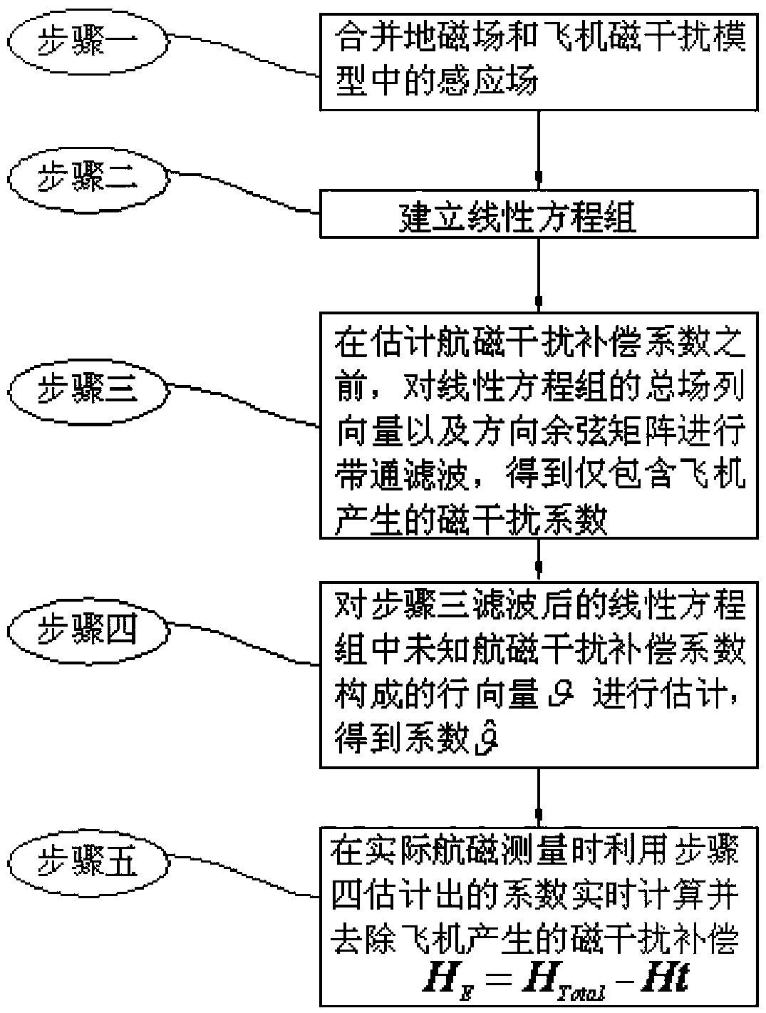
[0015] The aeromagnetic interference compensation method of the present embodiment combines figure 1 , the method is implemented through the following steps:

[0016] Step 1, merging the induction field in the geomagnetic field and the aircraft magnetic interference model;

[0017] Step 2, establishing a linear equation system between the total field column vector H and the row vector θ formed by unknown coefficients;

[0018] Step 3, before estimating the aeromagnetic interference compensation coefficient, band-pass filter the total field column vector and the direction cosine matrix of the linear equation system to obtain the magnetic interference coefficient that only includes the aircraft;

[0019] Step 4. Estimate the row vector θ formed by the unknown aeromagnetic interference compensation coefficients in the linear equation system filtered in step 3 to obtain the coefficients

[0020] Step 5. Use the coefficients estimated in Step 4 in the actual aeromagnetic survey...

specific Embodiment approach 2

[0021] Different from the specific embodiment 1, in the aeromagnetic interference compensation method of the present embodiment, the process of merging the geomagnetic field and the induction field in the aircraft magnetic interference model described in step 1 is as follows:

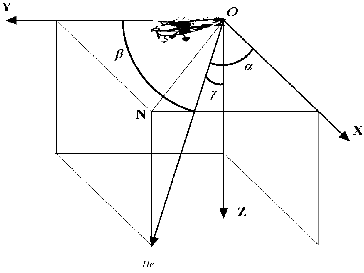
[0022] Step one, as attached figure 2 In the schematic diagram of the body coordinate system shown, the included angles between the geomagnetic field and the three axes of the body coordinate system are α, β, and γ respectively, and the corresponding direction cosines are respectively recorded as:

[0023] c x =cos(α)

[0024] c y =cos(β);

[0025] c z =cos(γ)

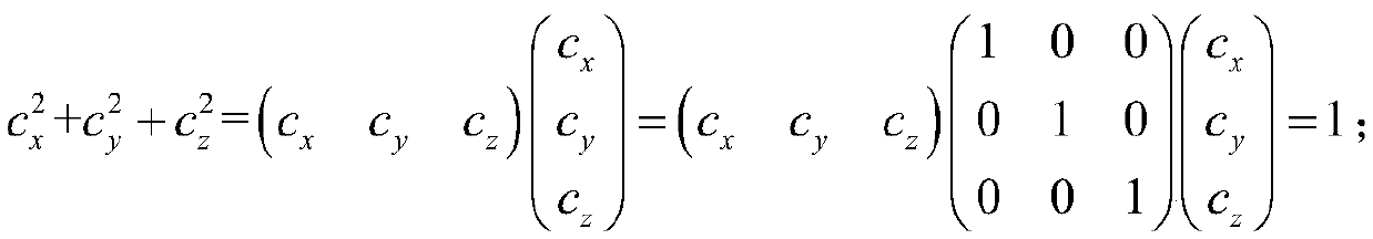
[0026] And satisfy the following relationship:

[0027] c x 2 + c y 2 + c z 2 = c x ...

specific Embodiment approach 3

[0043] Different from the first or second specific embodiment, in the aeromagnetic interference compensation method of this embodiment, the process of establishing the linear equation system between the total field column vector H and the row vector θ composed of unknown coefficients described in step 2 is,

[0044] Step 21. Record the total magnetic field measured by the total field magnetometer as H total , mainly including the geomagnetic field He and the constant field H generated by the aircraft platform per , induction field H induce and eddy current field H eddy These three kinds of magnetic disturbances are:

[0045] H T o t a l = H t + H ...


PUM


Abstract

The invention, which belongs to the aeromagnetic measurement field, provides an aeromagnetic interference compensation method. In the prior art, no geomagnetic filed processing method is provided during aeromagnetic interference compensation coefficient calculation according to the existing aeromagnetic interference compensation method, so that the estimated aeromagnetic interference compensation coefficient is not accurate. However, with the provided method, the technical problem can be solved. The method comprises: a geomagnetic field item and an induction field item in airplane magnetic interference are combined; a linear system of equations is established; before estimation of an aeromagnetic interference compensation coefficient, band-pass filtering is carried out on a general field column vector and a direction cosine matrix of the linear system of equations; an unknown aeromagnetic interference compensation coefficient in the linear system of equations after filtering is estimated; and during practical geomagnetic measurement, the magnetic interference generated by the airplane is calculated and removed in real time by using the estimated coefficient. With the method, the geomagnetic field component in the measured signal can be processed effectively, so that the estimation precision of the aeromagnetic interference compensation coefficient is improved and thus the precision of the aeromagnetic interference compensation result is enhanced.

Description

technical field [0001] The invention relates to an aeromagnetic interference compensation method. Background technique [0002] Aeromagnetic compensation technology is a technology to eliminate the magnetic interference of the aeronautical motion platform itself in the process of aeromagnetic detection. By analyzing the type and nature of the magnetic interference of the aviation motion platform itself, the mathematical model of the aeromagnetic interference is established, and then the total magnetic field and its three-component data are measured according to the prescribed method during the calibration flight, and then the mathematical model of the aeromagnetic interference is calculated. Compensation factor. During the compensation flight, that is, the actual aeromagnetic detection, the calculated compensation coefficient and aircraft attitude data are used to estimate the magnetic interference generated by the aeronautical motion platform and remove it from the total m...

Claims


Application Information

Patent Timeline
IPC IPC(8): G01R33/025
CPCG01R33/025
Inventor 韩琦赵冠一窦振家牛夏牧李琼王莘
Owner HARBIN INST OF TECH
Why Eureka
Try Eureka