Magnetic control time-delay device

A delay device and magnetic control technology, applied in electromagnetic relays, electromagnetic relay details, relays, etc., can solve problems such as poor reliability, complex mechanical structure, failure, etc., and achieve the effects of good reliability, small size, and rapid response.

Active Publication Date: 2014-09-10
CHONGQING MATERIALS RES INST
View PDF3 Cites 6 Cited by
  • Summary
  • Abstract
  • Description
  • Claims
  • Application Information

AI Technical Summary

Problems solved by technology

Generally, the delay device can be configured to include fixed contacts and movable contacts for accessing the circuit and a mechanical drive device for driving the movable contacts. The mecha

Method used


Image

  • Magnetic control time-delay device
  • Magnetic control time-delay device

Examples


Embodiment Construction

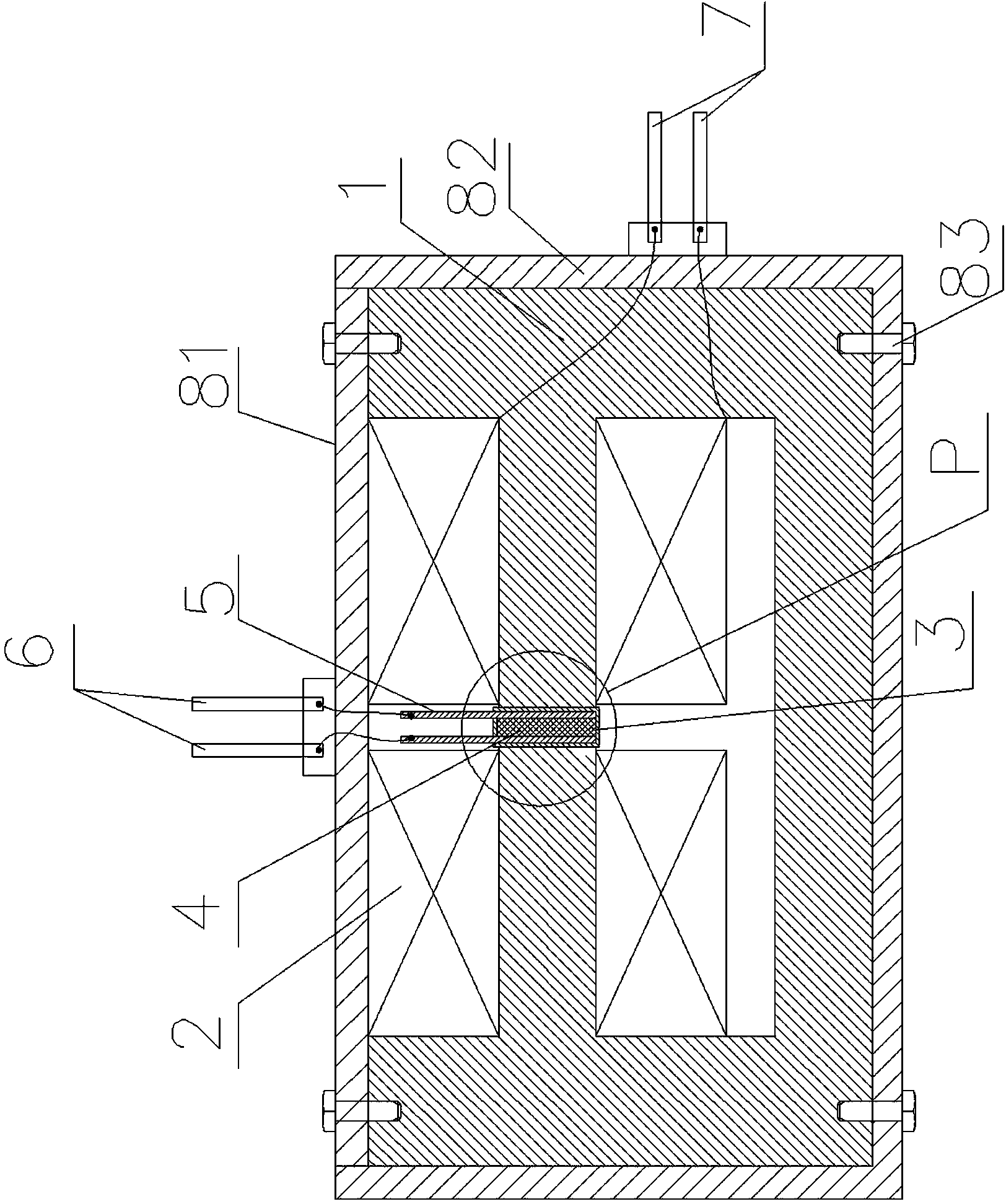
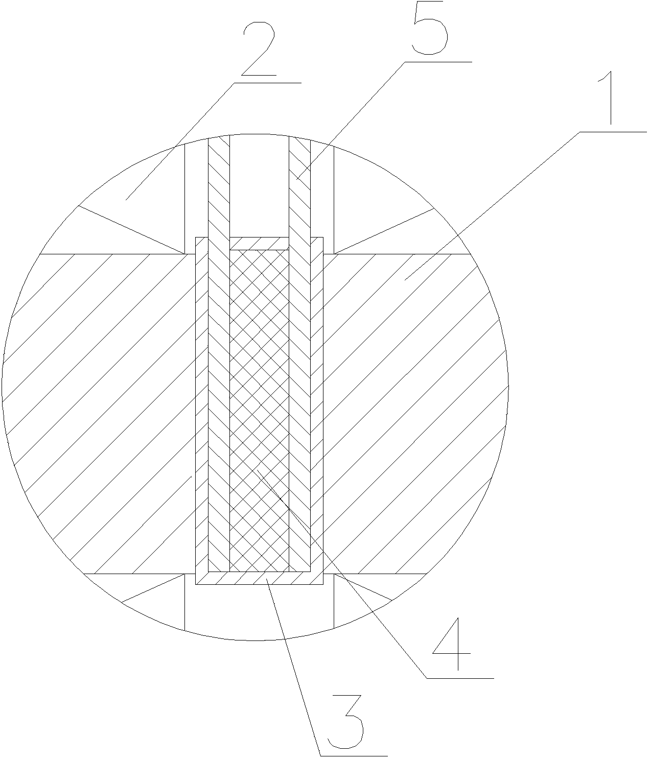
[0017] see figure 1 and figure 2 , a magnetic control delay device, including a semi-closed iron core 1 with an opening and an excitation coil 2 wound on the iron core, the two sides of the semi-closed iron core opening are magnetic poles, and the two magnetic poles are opposite to each other. The excitation coil described in this embodiment is wound on the magnetic poles on both sides of the semi-closed iron core opening. An insulating box 3 for setting magnetorheological cement 4 is fixed in the opening, and the insulating box is fixed between two magnetic poles. The insulating box is required to have a certain rigidity and cannot be deformed. The insulating box in this embodiment is bonded to the magnetic end surfaces on both sides of the semi-closed iron core opening. Electrode sheets are respectively provided on two sides corresponding to the magnetic poles inside the insulating box. The electrode sheet is fixed on the inner wall of the insulating box by bonding. Th...


PUM


Abstract

The invention relates to a magnetic control time-delay device which comprises a semi-closed iron core with an opening and a magnet exciting coil wound on the iron core. Magnetic poles are arranged on the two sides of the opening of the semi-closed iron core, the two magnetic poles correspond oppositely, an insulation box used for containing magneto-rheological plaster is fixed in the opening, the insulation box is fixedly arranged between the two magnetic poles, electrode slices are fixedly arranged on the two sides, corresponding to the magnetic poles, on the inner side of the insulation box respectively, the space between the two electrode slices is filled with the magneto-rheological plaster, the two electrode slices are respectively in full contact with the magneto-rheological plaster, and the magnet exciting coil, the iron core, the electrode slices and the magneto-rheological plaster form a closed magnetic circuit. The two electrode slices are respectively connected with a circuit access terminal through wires, and the two outgoing ends of the magnet exciting coil are respectively connected with a power source access terminal through wires. The device is simple in structure and good in reliability.

Description

technical field [0001] The invention relates to a time delay device, in particular to a magnetic control time delay device. Background technique [0002] As we all know, the delay device is a kind of opening and closing device used to delay the connection or cut-off of the circuit. Generally, the delay device can be configured to include fixed contacts and movable contacts for accessing the circuit and a mechanical drive device for driving the movable contacts. The mechanical drive device is similar to the mechanical drive device of a relay, and its mechanical structure is complex , and may fail under long-term working conditions, and the reliability is poor. Contents of the invention [0003] The object of the present invention is to provide a magnetically controlled time delay device with simple structure and good reliability in view of the shortcomings of the prior art. [0004] The object of the present invention is to adopt following scheme to realize: [0005] A m...

Claims


Application Information

Patent Timeline
IPC IPC(8): H01H50/86
Inventor 居本祥张登友杨百炼唐锐
Owner CHONGQING MATERIALS RES INST
Why Eureka
Try Eureka