Method for integrated preparing of foam metal phase change temperature control assembly

A technology of temperature control components and metal foam, applied in metal processing, metal processing equipment, manufacturing tools, etc., can solve the problems of short thermal response time, gap between metal foam and packaging container, affecting thermal response rate, etc., and achieve thermal response time Short, improve the thermal response rate, improve the effect of equivalent thermal conductivity

Inactive Publication Date: 2017-09-01
10TH RES INST OF CETC
View PDF7 Cites 7 Cited by
  • Summary
  • Abstract
  • Description
  • Claims
  • Application Information

AI Technical Summary

Problems solved by technology

[0017] The purpose of the present invention is to address the deficiencies of the existing phase change temperature control components, and provide a preparation of an integrated foam metal phase change temperature control electronic device component with higher thermal response rate, shorter thermal response time and better heat conduction effect Method, to solve the problem that there is a gap between the metal foam and the packaging container in the prior art phase change temperature control assembly, thereby affecting the thermal response rate

Method used


Image

  • Method for integrated preparing of foam metal phase change temperature control assembly
  • Method for integrated preparing of foam metal phase change temperature control assembly

Examples


Embodiment Construction

[0034] The present invention will be described in further detail below in conjunction with the accompanying drawings and embodiments, but the present invention is not limited to the scope of the described embodiments.

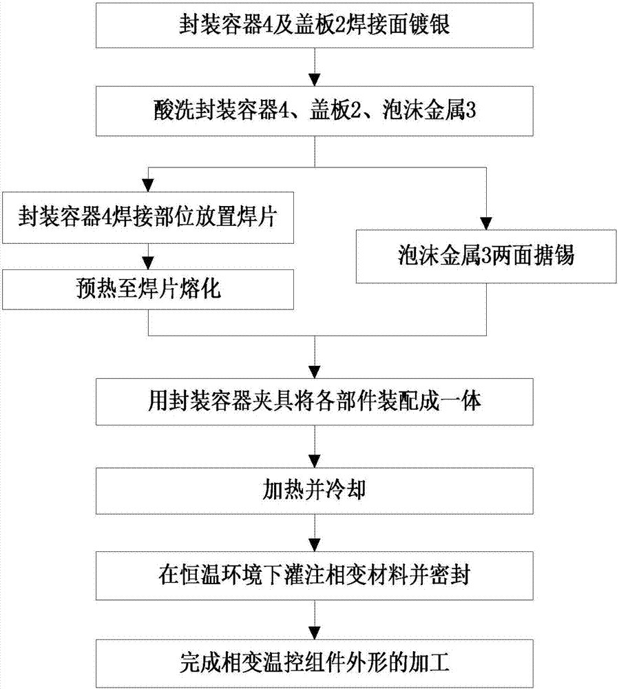
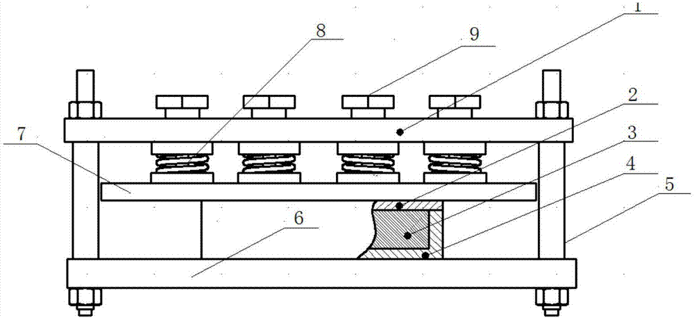
[0035] refer to figure 1 and figure 2 . According to the present invention, first prepare the packaging container fixture according to the external dimensions of the phase change temperature control assembly, pre-process the cavity for welding the foam metal 3 in the packaging container 4, and weld the cavity and the cover plate 2 on the welding surface Pre-plating with silver, and then laying a layer of solder sheet on the welding surface in the cavity of the packaging container 4, preheating the packaging container and the packaging container fixture until the solder sheet is completely melted; compressing the foam metal 3 to the size of the cavity and placing the metal foam 3 on the , the lower contact interface is tinned; the foam metal 3, the packaging ...


PUM

PropertyMeasurementUnit
pore sizeaaaaaaaaaa
particle diameteraaaaaaaaaa
densityaaaaaaaaaa

Abstract

The invention provides a method for integrated preparing of a foam metal phase change temperature control assembly and aims at providing a technology method for solving the problem that in a phase change temperature control assembly, a gap exists between foam metal and a base body material, and the heat response rate is influenced. The method is achieved through the following technical scheme that according to the boundary dimension of a packaging container, a packaging container clamp is prepared; a cavity used for welding the foam metal is machined in the packaging container in advance, a layer of welding piece is laid on the inner side welding face of the cavity of the packaging container, and the contact interface of the foam metal is subjected to tin lining; the foam metal is compressed to the cavity size; the packaging container, the foam metal and the clamp are assembled into a whole and heated, and after cooling, a formed phase change temperature control assembly blank is taken out of the clamp of the packaging container; in the constant-temperature environment, a liquid phase change material is poured into the phase change temperature control assembly from a pouring port in the bottom of the packaging container; and finally, the pouring port is sealed, and machining of the appearance of the temperature control assembly is finished.

Description

technical field [0001] The invention relates to a phase change temperature control component in the field of thermal control of electronic devices and a preparation method for integrated forming thereof, belonging to the field of phase change temperature control of electronic devices. Background technique [0002] Generally, electronic devices need to work within a certain temperature range, but electronic devices will generate a certain amount of heat during operation, which will cause their temperature to rise continuously. If the temperature exceeds the allowable temperature range, the electronic device or chip will fail, reducing the reliability of the system. sex. A statistical report points out that more than half of electronic device failures are caused by temperature. The research results show that the temperature of electronic components is lowered by 1°C from the normal working temperature level, and the failure rate can be reduced by 4%; if it is increased by 10-...

Claims


Application Information

Patent Timeline
Patent Type & Authority Applications(China)
IPC IPC(8): B23K1/005B23K1/19B23K1/20B23K3/04H05K7/20B23K101/36
CPCB23K1/0056B23K1/19B23K1/20B23K3/04B23K2101/36H05K7/20
Inventor 苏欣谢义水
Owner 10TH RES INST OF CETC
Why Eureka
Try Eureka