Powered cartridges and other devices within housings

a technology of power supply and housing, which is applied in the direction of electrostatic separation, machines/engines, solid separation, etc., can solve the problems of inductive field interference and impracticality of wires inside the housing, and achieve the effect of reducing the risk of poor connection and increasing the useable life of the overall system

Active Publication Date: 2008-04-17
MILLIPORE CORP
View PDF20 Cites 22 Cited by
  • Summary
  • Abstract
  • Description
  • Claims
  • Application Information

AI Technical Summary

Benefits of technology

[0010]The shortcomings of the prior art are overcome by the present invention, which describes a system and method for supplying electrical power to a device, such as a filter element or an electrical component thereon, located within a housing. In some cases, the use of wires inside the housing may be impractical, due to internal conditions, such as fluid flow, pressure or temperature. This invention requires no physical connections between the power source and the one or more enclosed electronic components, thereby reducing the risk of poor connections, and increasing the useable life of the overall system. In one embodiment, a housing adapted to receive a filter element in the form of a filtration cartridge, such as that commercially available from Millipore Corporation and sold under the name Filter Cartridge Housing Series 3000, is provided, and a conductive coil is positioned in the housing base, and a second coil is positioned in the filter element. Current is then passed through the coil in the housing base. Through induction, a current is created in the second coil in the filter element, in much the same way as a transformer functions. This transfer for power requires no physical electrical connection and also places no limits on the amount of power that can be induced in the filter element coil. In a second embodiment, the filter element comprises tangential flow filtration (TFF) cassettes, and one or more coils are placed within the cassettes to achieve the same result. The inductive field may interfere with the operation of the various electronic functions, such as communications, sensing or other activities. To overcome this issue, an energy storage component, such as a capacitor, is included in the filter electronics. In this way, the power generated by the inductive field can be stored, and used when the inductive field is no longer present.

Problems solved by technology

In some cases, the use of wires inside the housing may be impractical, due to internal conditions, such as fluid flow, pressure or temperature.
The inductive field may interfere with the operation of the various electronic functions, such as communications, sensing or other activities.

Method used


Image

  • Powered cartridges and other devices within housings
  • Powered cartridges and other devices within housings
  • Powered cartridges and other devices within housings

Examples


Embodiment Construction

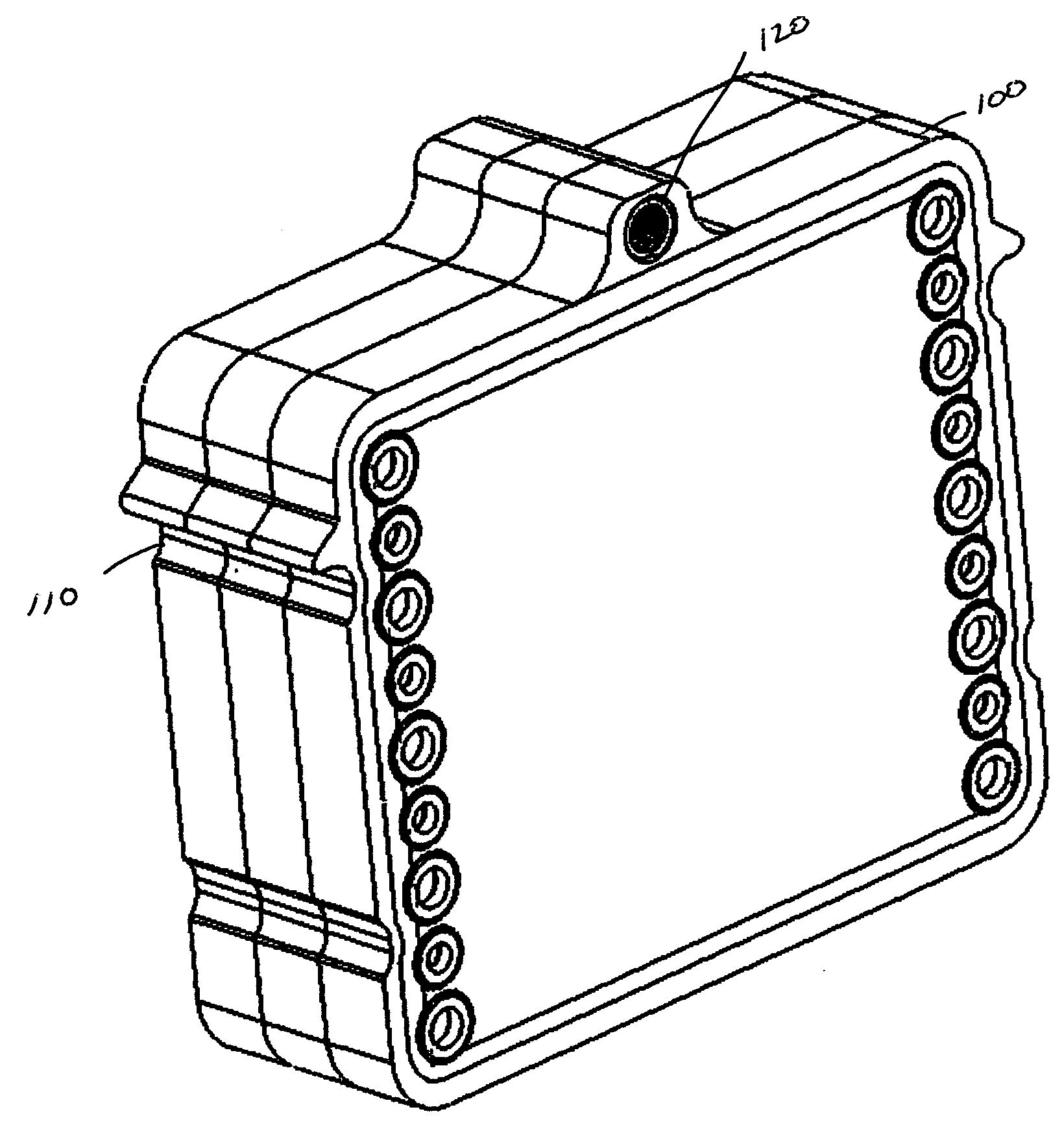
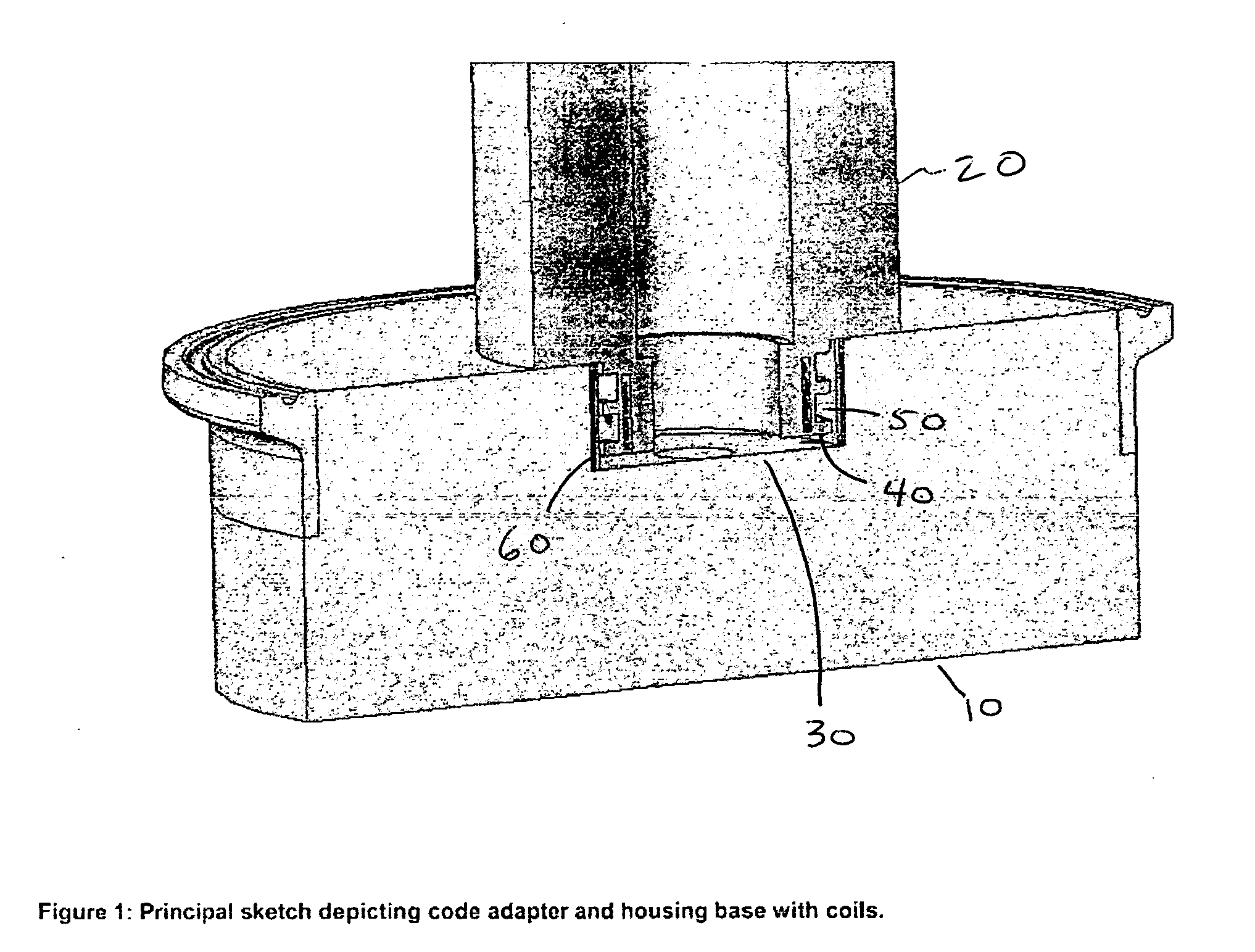
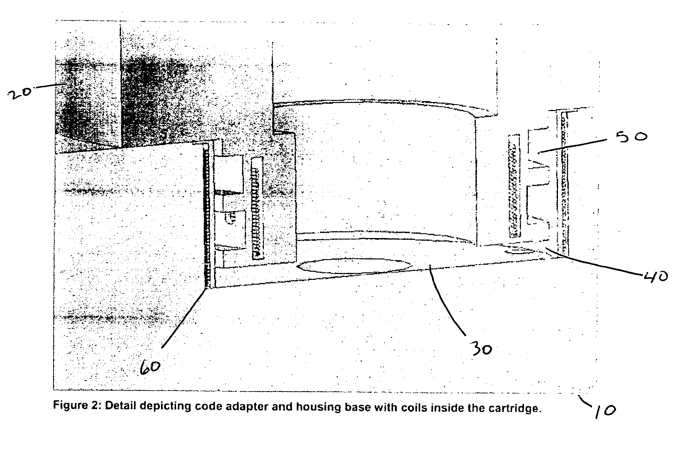
[0017]FIG. 1 illustrates a representative filter housing base 10 and an associated filter element 20. In the embodiment shown, the base and filter element are that of a device Cartridge Filter and Series 3000 Housing, commercially available from Millipore Corporation. The filter element has a membrane, through which materials are passed, and the corresponding structure or frame necessary to support this membrane. Surrounding this assembly is typically a housing dome, preferably constructed of stainless steel or some other non-corrosive material. Also, inlets and outlets are typically present, but have been omitted from FIG. 1 for clarity. Housing base 10 typically contains one or more matable portions, such as cavities 30, each adapted to mate with and hold a filter element. These cavities typically have one or more inlet and output ports in them, to allow fluid to pass through the filter element. Into this cavity 30, a filter element 20 is inserted. The filter element 20 preferably...


PUM

PropertyMeasurementUnit
electrical conductiveaaaaaaaaaa
store energyaaaaaaaaaa
poweraaaaaaaaaa

Abstract

The present invention describes a system and method for supplying electrical power to a device, such as a filter element, located within a housing. In one embodiment, a conductive coil is embedded into the housing base, and a second coil is embedded into the filter element. Current is then passed through the coil in the housing base. Through induction, a current is created in the second coil in the filter element, in much the same way as a transformer functions. This inductive field may interfere with the operation of the various electronic functions, such as communications, sensing or other activities. To overcome this issue, an energy storage component, such as a capacitor, is included in the filter electronics. In this way, the power generated by the inductive field can be stored, and used when the inductive field is no longer present.

Description

BACKGROUND OF THE INVENTION[0001]The use of wireless communication has become prevalent, especially in the management of assets, particularly those applications associated with inventory management. For example, the use of RFID tags permits the monitoring of the production line and the movement of assets or components through the supply chain.[0002]To further illustrate this concept, a manufacturing entity may adhere RFID tags to components as they enter the production facility. These components are then inserted into the production flow, forming sub-assemblies in combination with other components, and finally resulting in a finished product. The use of RFID tags allows the personnel within the manufacturing entity to track the movement of the specific component throughout the manufacturing process. It also allows the entity to be able to identify the specific components that comprise any particular assembly or finished product.[0003]In addition, the use of RFID tags has also been a...

Claims


Application Information

Patent Timeline
Patent Type & Authority Applications(United States)
IPC IPC(8): B01D35/14
CPCB01D35/143B01D46/429H02J5/005B01D2201/56B01D2201/58B01D2201/52H02J50/70H02J50/402H02J50/10H02J50/005
Inventor GRZONKA, MICHAEL T.BURKE, AARON
Owner MILLIPORE CORP
Why Eureka
Try Eureka