Contactless data communication system and contactless IC tag

a communication system and data technology, applied in the field of contactless data communication system and contactless ic tag, can solve the problems of increasing the amount of tags to be discarded, increasing the cost of the entire system, and not including the option to determine in the known system, so as to increase the credibility of displayed contents, reduce the cost of the entire system, and reduce the number of tags disposed.

Inactive Publication Date: 2008-03-13
SEIKO EPSON CORP
View PDF4 Cites 19 Cited by
  • Summary
  • Abstract
  • Description
  • Claims
  • Application Information

AI Technical Summary

Benefits of technology

[0010]An advantage of the invention is to provide a contactless data communication system which allows a cost reduction of the entire system without requiring time for exchanging the contactless IC tags in a distribution phase or a testing phase, and without increasing the number of tags disposed.
[0011]Another advantage of the invention is to provide a contactless data communication system which increases the credibility of the displayed contents, so that the display of the contactless IC tag adhered to the container and the fluid contained therein always matches, even after the fluid is replaced.
[0012]Another advantage of the invention is to provide a contactless data communication system at low cost, without involving the remaking of the internal structure of the contactless IC tag into a specific packaging structure, even when the communication range between the contactless IC tag and the reader-writer is short.
[0013]Yet another advantage of the invention is to provide a novel contactless IC tag suitably used for such contactless data communication system.
[0014]According to a first aspection of the invention, a contactless data communication system includes: a first and a second contactless integrated circuit tags each including an unique identifier; and a reader-writer for reading out and writing in data in a contactless state with the first and the second contactless integrated circuit tags. The first integrated circuit tag includes: a data detection unit for detecting data; a data determination unit for determining data detected by the data detection unit; and a data transmission unit for transmitting a determination result of the data determination unit to the second contactless integrated circuit tag. Here, the reader-writer and the first and the second contactless integrated circuit tags performing a contactless data communication therebetween, using an induction field; and the first contactless integrated circuit tag creating an electrical power from the induction field generated bay the reader-writer, and utilizing the electrical power so as to perform a contactless data communication with the second contactless integrated circuit tag.
[0015]In such contactless data communication system, the data determination unit determines the data detected by the detection unit of the first contactless IC tag, and the determination result is transmitted to the second contactless IC tag through the data transmission unit. At this time, the first contactless IC tag creates an electrical power from an induction field generated by the reader-writer, and communicates with the second contactless IC tag by utilizing this electrical power. Thereafter, the second contactless IC tag receives the data transmitted through the data receiving unit from the first contactless IC tag, and carries out a display with the display unit based on that received data.

Problems solved by technology

In such case, the cost of the entire system increases, since it is time consuming to exchange the contactless IC tags in a distribution phase or a testing phase, and the amount of tags to be discarded increases.
Moreover, known systems do not include the option to determine whether or not the fluid in the container and the display of the contactless IC tag adhered to the container really matches.
Still further, the communication range becomes short between the contactless IC tag and the reader-writer, when fluids are contained inside the containers, therefore requiring to remake the internal structure of the contactless IC tag into a specific packaging structure, also resulting in cost increase.

Method used


Image

  • Contactless data communication system and contactless IC tag
  • Contactless data communication system and contactless IC tag
  • Contactless data communication system and contactless IC tag

Examples


first embodiment

[0058]The first embodiment of the invention will now be described with reference to FIGS. 1 through 8.

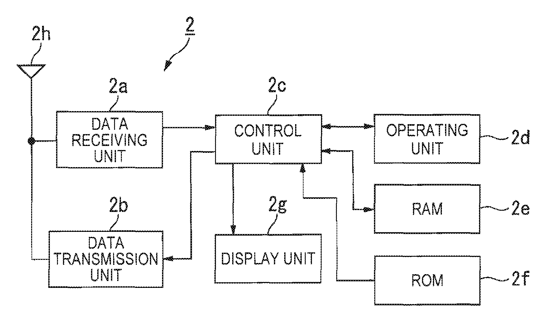
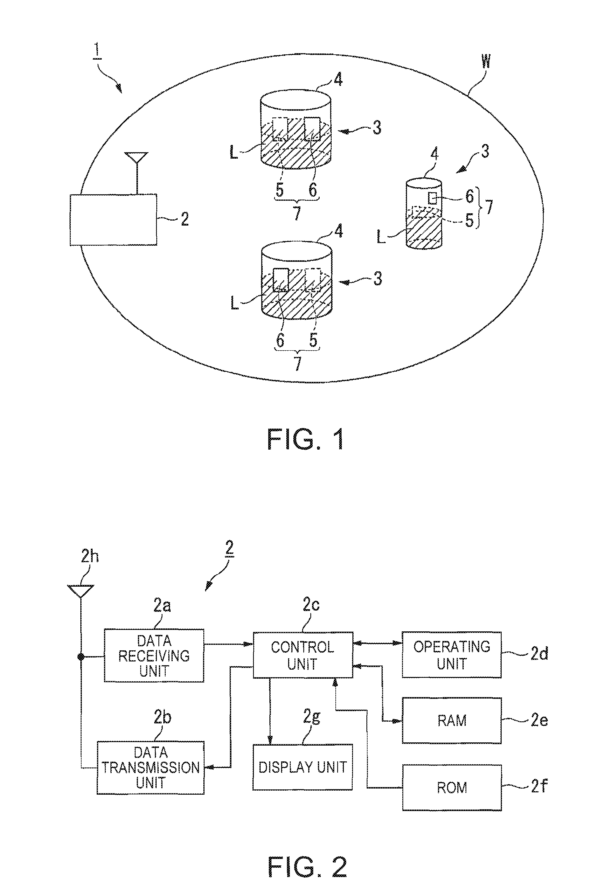
[0059]FIG. 1 is a block diagram showing the structure of a contactless data communication system 1 according to the embodiments of the invention.

[0060]This contactless data communication system 1 includes, as shown in FIG. 1, a reader-writer 2, and a plurality of contactless IC tags 3. The contactless data communication is performed therebetween, utilizing an induction field W.

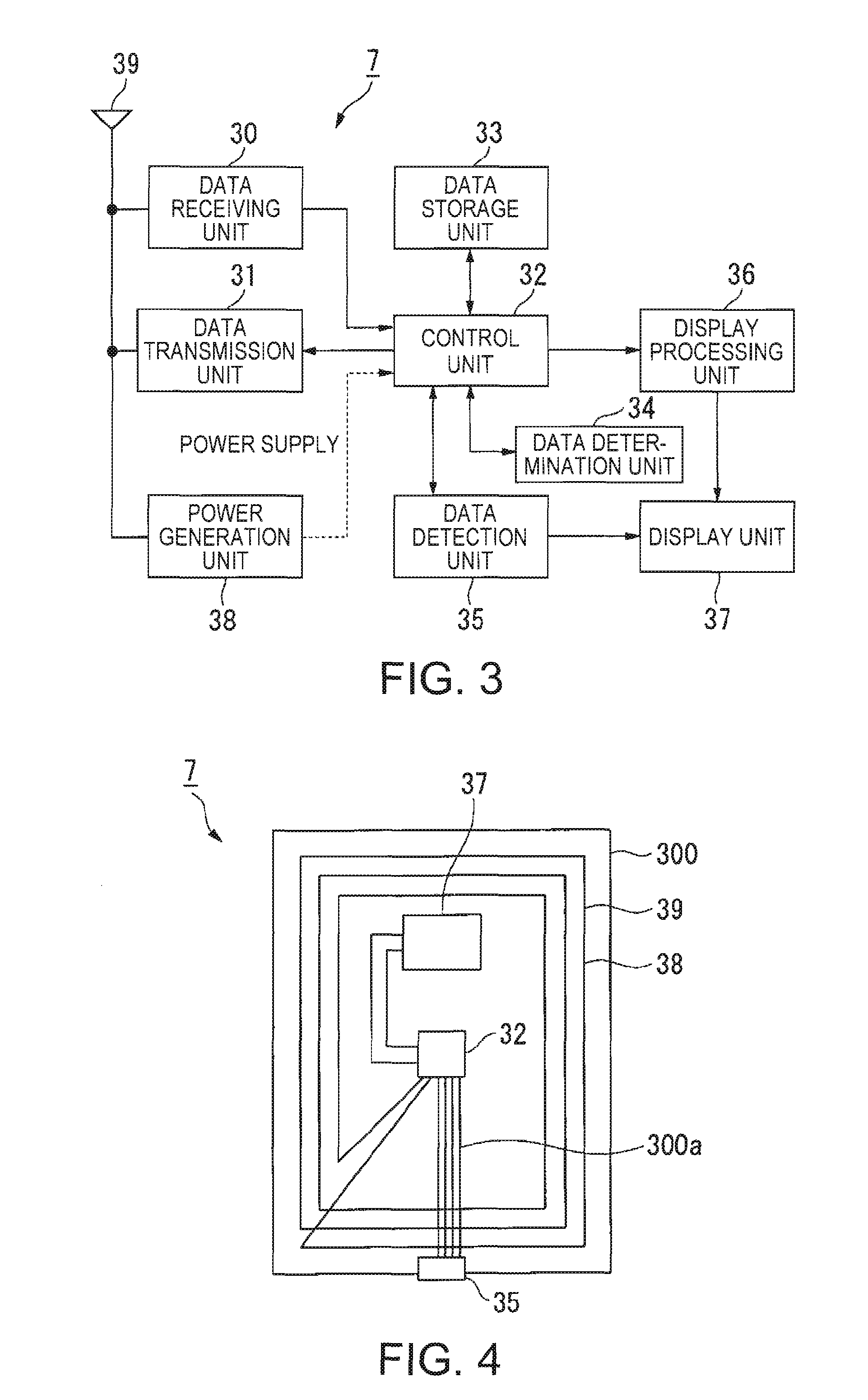
[0061]Further, this contactless data communication system 1 includes a first contactless IC tag 5 (hereafter referred to as “internal tag 5”) that is adhered to the inside of a container 4, and a second contactless IC tag 6 (hereafter referred to as “external tag 6”) that is adhered to the outside the container 4. The internal tag 5 includes a biosensor for detecting a solution L accommodated in the container 4, and the external tag 6 includes a display device which allows nonvolatile display for displaying th...

second embodiment

[0137]The second embodiment of the invention will now be described with references to FIG. 9.

[0138]The same signs and numerals are used for the parts equivalent to those in the first embodiment, and the description is omitted.

[0139]The contactless data communication system 1 shown as the second embodiment sets an access code from the reader-writer 2 to the contactless IC tag 7, so as to check if the access code matches the code set in advance in the contactless IC tag 7, prior to retrieving the data from the detection unit 35 serving as a sensor. If the access code does not match, the system displays the access record of the reader-writer 2 as a display data in the display unit 37. This is where the second embodiment differs from the first embodiment. The structures of the reader-writer 2 and the contactless IC tag 7 are the same as those of the first embodiment.

[0140]FIG. 9 is a flowchart illustrating the processing conducted from the moment the reader-writer 2 sends the sensing re...


PUM


Abstract

A contactless data communication system includes: a first and a second contactless integrated circuit tags each including an unique identifier; and a reader-writer for reading out and writing in data in a contactless state with the first and the second contactless integrated circuit tags. The first integrated circuit tag includes: a data detection unit for detecting data; a data determination unit for determining data detected by the data detection unit; and a data transmission unit for transmitting a determination result of the data determination unit to the second contactless integrated circuit tag. Here, the reader-writer and the first and the second contactless integrated circuit tags performing a contactless data communication therebetween, using an induction field; and the first contactless integrated circuit tag creating and electrical power from the induction field generated by the reader-writer, and the utilizing the electrical power so as to perform a contactless data communication with the second contactless integrated circuit tag.

Description

[0001]The entire disclosure of Japanese Patent Application Nos. 2006-245167, filed Sep. 11, 2006 and 2007-208973, filed Aug. 10, 2007 are expressly incorporated by reference herein.BACKGROUND[0002]1. Technical Field[0003]Several aspects of the present invention relate to a contactless data communication system for carrying out contactless data communications between a contactless IC tag and a reader-writer using an induction field, as well as to a contactless IC tag used in such communication.[0004]2. Related Art[0005]It is known that contactless data communication systems utilize an induction filed for contactless data communications between a contactless IC tag adhered to a commodity and a reader-writer, so as to read an unique identification provided to the contactless IC tag. Such contactless communication systems are widely applied to systems such as an inventory management system for controlling commodity inventories and a logistics system for read / write history data in distri...

Claims


Application Information

Patent Timeline
Patent Type & Authority Applications(United States)
IPC IPC(8): H04B7/00
CPCH04B5/0031H04B5/02H04B5/0056G06K17/00G06K19/07
Inventor HOSHINA, MASAKI
Owner SEIKO EPSON CORP
Why Eureka
Try Eureka