Eraser assembly for a rotary tool

a technology of eraser assembly and rotary tool, which is applied in the direction of erasing devices, gear teeth, gear teeth, etc., can solve the problems of difficult replacement of eraser disks, complex number of steps, and inability to replace eraser disks easily, so as to achieve quick and convenient replacement.

Inactive Publication Date: 2012-10-16
DYNABRADE
View PDF31 Cites 2 Cited by
  • Summary
  • Abstract
  • Description
  • Claims
  • Application Information

AI Technical Summary

Benefits of technology

[0007]The invention therefore relates principally to an eraser assembly that allows for prompt removal of worn eraser disks from an eraser hub, and for quick and convenient reinstallation of replacement disks onto the hub without requiring the use or assistance of any hand held tools whatsoever in the process.
[0008]Accordingly, it is a principal object of the present invention to provide for an eraser assembly for a rotary tool comprising an eraser disk and an eraser hub for mounting and holding the eraser disk. The eraser hub includes upper and lower surfaces, wherein the eraser hub upper surface features a centrally positioned throughbore, a flange at the peripheral edge of the hub and a stub shaft on the lower surface positioned axially with the throughbore. The eraser hub includes a plurality of spaced apertures or slots for engaging with and detachably locking the eraser disk so it is flush with the eraser hub. The eraser disk is preferably comprised of a polymeric composition, such as an elastomeric material or other durable, resilient material, and comprises an upper surface and lower surface opposite the upper surface. The upper surface of the eraser disk includes a central recess and a aperture in the recess keyed for axial alignment with the throughbore of the eraser hub. The eraser disk is also equipped with a plurality of teeth running radially from the central recess to the peripheral edge thereof. The lower surface opposite the upper surface of the eraser disk further comprises a plurality of mounting elevations or protrusions keyed for engaging with the spaced apertures or slots in the eraser hub for securely locking the eraser disk to the eraser hub, avoiding slippage of the eraser disk during operation.

Problems solved by technology

Eraser disks of this type tend to become deformed over time, and consequently, lose their efficiency.
However, as mentioned in Montabaur et al., eraser disks are not easily replaceable.
This complicated number of steps is not time efficient, especially when eraser disks need to be replaced frequently.
However, Winter et al. fail to disclose an eraser disk that is quickly replaceable.
Attaching the disk in this manner takes added time and is an inconvenience for the user to replace the eraser disk.

Method used


Image

  • Eraser assembly for a rotary tool
  • Eraser assembly for a rotary tool
  • Eraser assembly for a rotary tool

Examples


Embodiment Construction

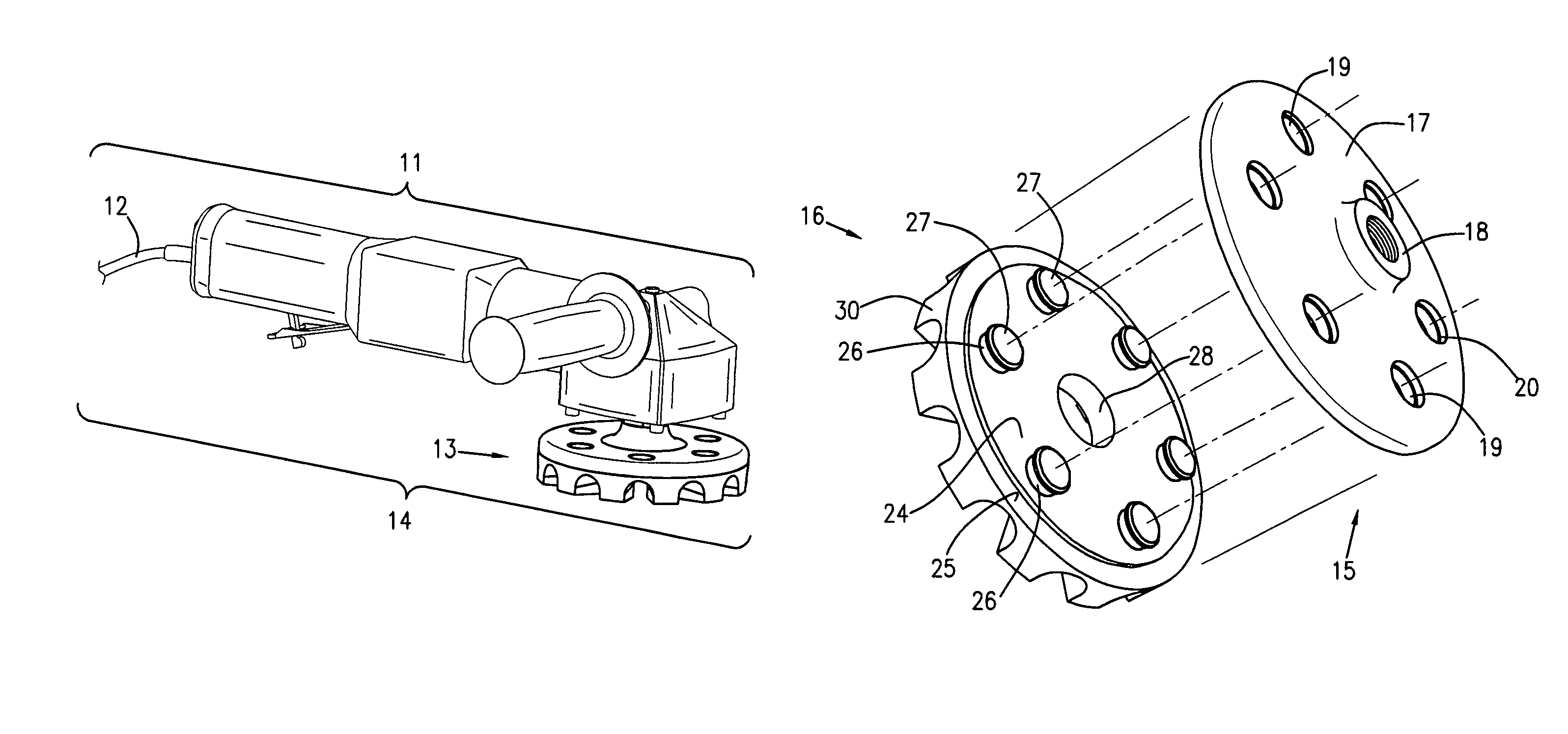
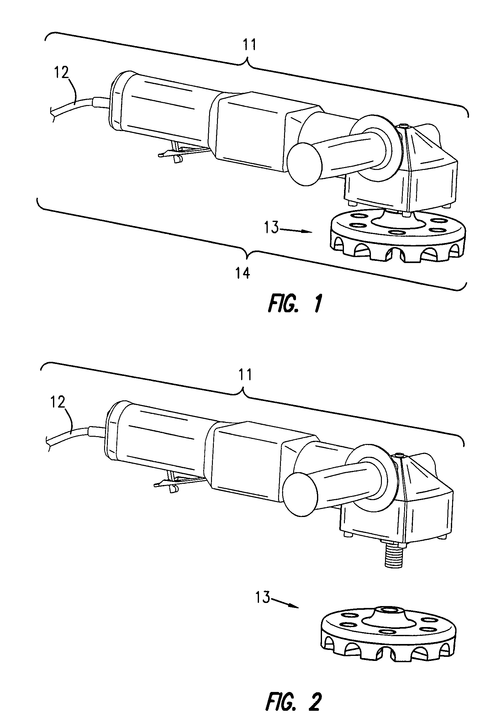
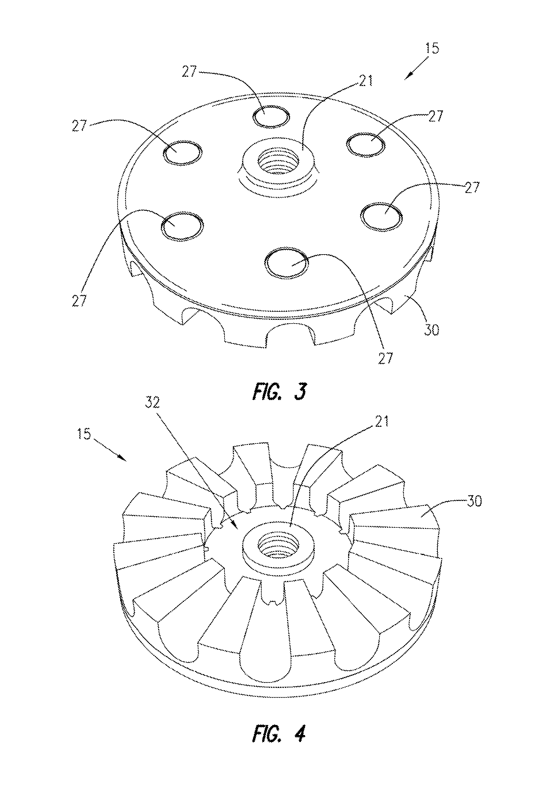
[0034]At the outset, it should be appreciated that like drawing numbers on different drawing views identify identical structural elements of the invention. While the present invention is described with respect to what is presently considered to be the preferred embodiments, it is understood that the invention is not limited to the disclosed embodiments.

[0035]Furthermore, it is to be understood that this invention is not limited to the particular methodology, materials and modifications described and as such may, of course, vary. It is also to be understood that the terminology used herein is for the purpose of describing particular embodiments only, and it is not intended to limit the scope of the present invention, which will be limited only by the appended claims.

[0036]Unless defined otherwise, all technical and scientific terms used herein have the same meaning as commonly understood to one of ordinary skill in the art to which this invention belongs. Although any methods, device...


PUM

PropertyMeasurementUnit
widthaaaaaaaaaa
heightaaaaaaaaaa
speedsaaaaaaaaaa

Abstract

A two piece eraser assembly , including an eraser disk and an eraser hub for mounting and holding the eraser disk. The eraser hub includes upper and lower surfaces a flange at the peripheral edge of the hub and a stub shaft on the lower surface positioned axially with a throughbore. The eraser hub includes a plurality of spaced apertures for engaging with and detachably locking eraser disk extensions on the backside. The upper surface of the eraser disk includes a central recess and an aperture in the recess. The eraser disk includes a plurality of abrading teeth running radially from the central recess. The lower surface of the eraser disk further comprises a plurality of mounting elevations keyed for engaging with the spaced apertures or slots in the eraser hub for securely locking the eraser disk to the eraser hub.

Description

FIELD OF THE INVENTION[0001]The present invention relates to rotary abrading tools. More specifically, the present invention relates to rotary abrading tools of the erasure type.BACKGROUND OF THE INVENTION[0002]Rotary abrading tools of the erasure type are well known and typically comprise a rotary driven annular disk made of an elastomeric material, commonly referred to as an “eraser wheel” or an “eraser disk.” Rotary abrading tools of the erasure type are used to remove adhesive material, such as paint and decals, from metal surfaces. An eraser disk is rotated at high speeds and pressed against adhesive material for removal. Eraser disks of this type tend to become deformed over time, and consequently, lose their efficiency. Therefore, eraser disks need to be replaced frequently, often during the course of completing a single project.[0003]In U.S. Pat. No. 5,259,914, Fisher discloses a disk-shaped eraser unit with a flat disk embedded inside the eraser member. The disk has a centr...

Claims


Application Information

Patent Timeline
Patent Type & Authority Patents(United States)
IPC IPC(8): B24B23/02B43L19/00
CPCB24B23/028B24D13/14Y10T156/1972
Inventor LAMPKA, MARKGILES, MATTHEW A.
Owner DYNABRADE
Why Eureka
Try Eureka