Liquid discharge apparatus with platen and platen moving device and method for controlling the same

a technology of moving device and liquid discharge apparatus, which is applied in the direction of power drive mechanism, inking apparatus, printing, etc., can solve the problems of affecting the design of the platen, affecting the function of the supporting paper sheet, and difficulty in securing the retracting spa

Active Publication Date: 2012-10-16
BROTHER KOGYO KK
View PDF20 Cites 5 Cited by
  • Summary
  • Abstract
  • Description
  • Claims
  • Application Information

AI Technical Summary

Benefits of technology

[0007]The present invention has been made in order to solve the problems as described above, an object of which is to provide a liquid discharge apparatus in which a construction for retracting the platen can be designed more freely, without making the installation space for the liquid discharge apparatus be great, and to provide a controlling method for the liquid discharge apparatus.

Problems solved by technology

However, the platen is divided into two portions, and the two divided portions are retracted to upstream and downstream sides, respectively, of the “paper transporting direction”, which in turn makes it difficult to secure a retracting space for retracting the platen while avoiding interference with other part or component, thereby resulting in a problem such that the “freedom in designing the platen” is considerably limited.
Accordingly, in order to prevent the platen from interfering with the rollers, the platen has to be designed to have a narrow width (namely, length in the transporting direction); and thus there is a fear that the function for supporting the paper sheet might be compromised or lowered.
Further, in the construction in which the two divided portions of the platen are rotatable or pivotable, it is necessary that the platen is arranged to be sufficiently away from the nozzle surface such that the platen is prevented from contacting with the nozzle surface; and thus there is a fear that the discharge characteristic might be lowered or lost.

Method used


Image

  • Liquid discharge apparatus with platen and platen moving device and method for controlling the same
  • Liquid discharge apparatus with platen and platen moving device and method for controlling the same
  • Liquid discharge apparatus with platen and platen moving device and method for controlling the same

Examples


first embodiment

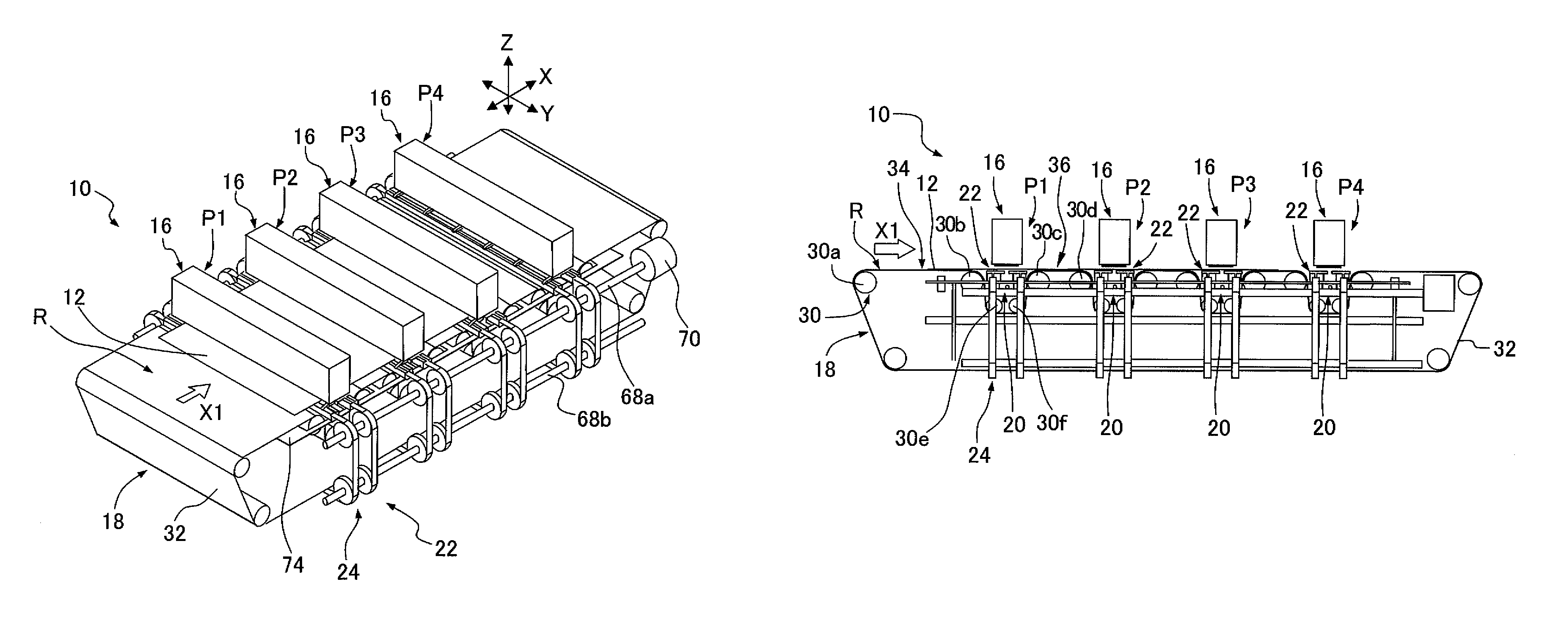
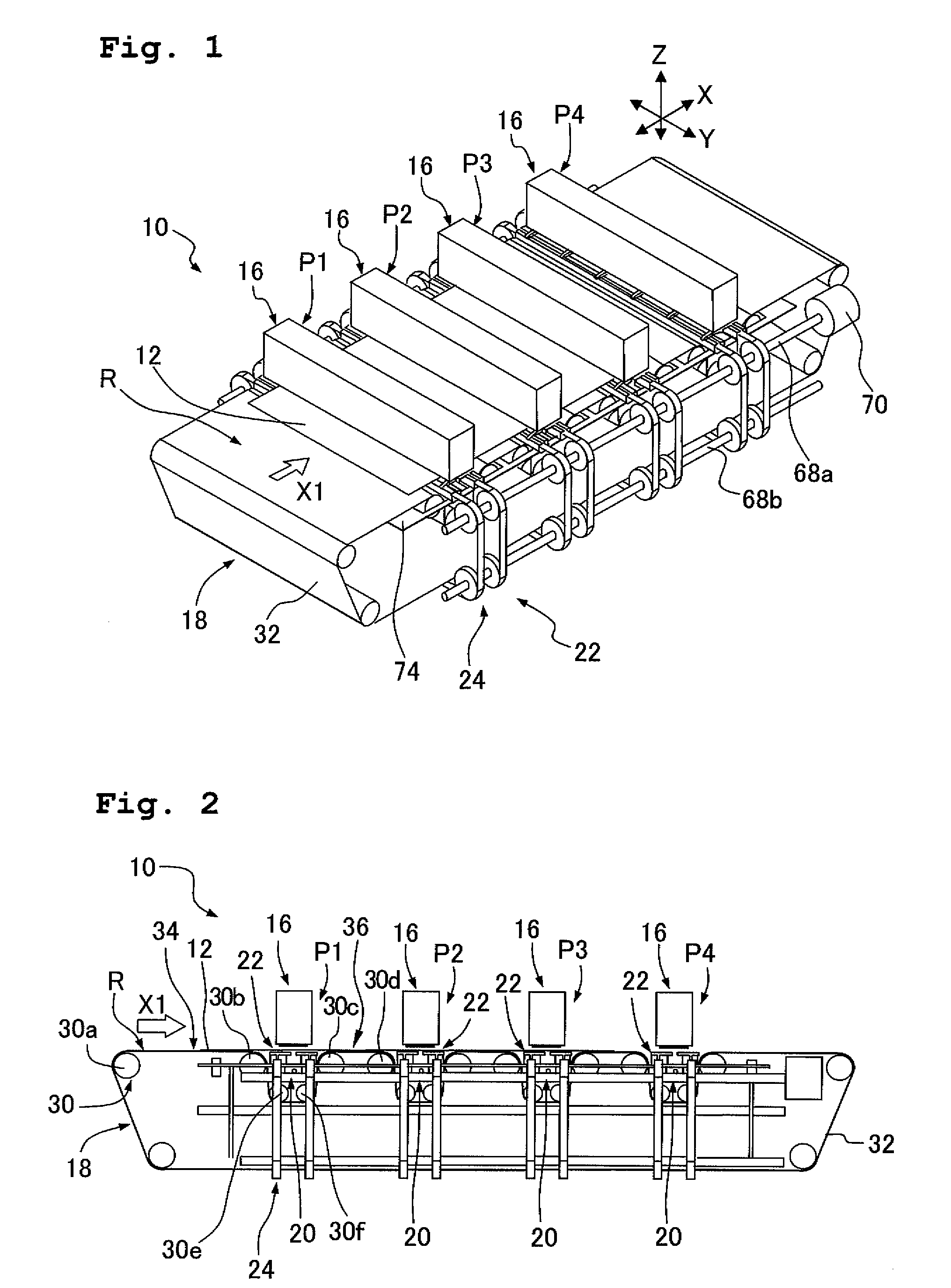
[0033]As shown in FIGS. 1 and 2, an ink discharge apparatus 10 is provided with a plurality of pieces of (four in the embodiment) ink-discharge line head 16 as the “liquid discharge head (head)” having a plurality of nozzles 14 (FIG. 4) through which an ink is discharged toward a paper sheet 12 as the “discharge-objective (object)”; a transporting device 18 which transports the paper sheet 12 to the ink-discharge line heads 16; a platen 22 (FIG. 2) which supports the paper sheet 12 at a position facing the plurality of nozzles 14; and a platen driving device (platen moving device) 24 which drives (moves) the platen 22. Further, the ink discharge apparatus 10 of the embodiment is provided with a cap device 20 (FIG. 2) which covers the plurality of nozzles 14 as necessary. In this embodiment, as shown in FIGS. 1 and 2, a transporting route R for transporting the paper sheet 12 is formed or defined by the transporting device 18; and in the transporting route R, four pieces of the ink-d...

second embodiment

Construction of Ink Discharge Apparatus According to the Second Embodiment

[0069]The ink discharge apparatus of the second embodiment is constructed in a similar manner as the ink discharge apparatus 10 of the first embodiment, except that a spur roller unit 110 is additionally provided on the ink discharge apparatus 10 of the first embodiment as shown in FIGS. 11A and 11B; that a space T is secured for arranging the spur roller unit 110 at a corner portion in the transporting direction X, the corner portion being located below or under the ink-discharge line head 16, as shown in FIG. 12A; and that the height of the platen 22 is adjusted at least in three steps.

[0070]To focus attention to one of the four head positions P1 to P4, as shown in FIG. 12A, one piece of the spur roller unit 110 is provided with respect to one piece of the platen 22 to face or be opposite to the platen 22. The spur roller unit 110 has one spur roller holder 112, six spur rollers 114 and six urging springs 11...

third embodiment

Construction of Ink Discharge Apparatus According to the Third Embodiment

[0075]The ink discharge apparatus of the third embodiment is constructed in a similar manner as the ink discharge apparatus 10 of the first embodiment, except that a wiper 120 is additionally provided on each of the platen belt 66, as shown in FIG. 14.

[0076]The ink discharge apparatus of the third embodiment is capable of performing a cleaning operation by bringing the wiper 120 into contact with the nozzle surface 42a to thereby remove, off the nozzle surface 42a, a stain or dirt such as the ink adhered to the nozzles surface 42a. The wiper 120 has a shape similar to that of the attachment portion 80 shown in FIG. 7, and the wiper 120 is formed, for example, of an elastic material such as rubber, a resin having flexibility (such as elastomer), etc. such that the nozzle surface 42a is hardly damaged or harmed and that the stain can be easily removed. One piece of the wiper 120 is provided on each of the platen ...


PUM


Abstract

A liquid discharge apparatus includes: a head having a nozzle surface having a plurality of nozzles which are open in the nozzle surface and through which a liquid is discharged toward an object; a transporting device which transports the object relative to the nozzle surface in a transporting direction and which positions the object to face the nozzle surface; a platen having a flexibility or bendability and provided with an attachment portion to which the object is attached; and a platen moving device which moves the platen in a direction orthogonal to the transporting direction to position the attachment portion at a nozzle facing position facing the nozzle surface under the condition that the liquid is discharged toward the object.

Description

CROSS REFERENCE TO RELATED APPLICATION[0001]The present application claims priority from Japanese Patent Application No. 2009-087433 filed on Mar. 31, 2009, the disclosure of which is incorporated herein by reference in its entirety.BACKGROUND OF THE INVENTION[0002]1. Field of the Invention[0003]The present invention relates to a liquid discharge apparatus in which a platen is arranged at a position facing a nozzle surface of a liquid discharge head, and to a controlling method for controlling the liquid discharge apparatus.[0004]2. Description of the Related Art[0005]In a conventional technique, the platen is constructed to be movable and a driving device is attached to a body of the apparatus (casing, etc.); and upon performing the cleaning, the platen is moved by the driving device in a “transporting direction in which the paper or paper sheet is transported (paper-sheet transporting direction)”, thereby retracting or withdrawing the platen from the position facing the nozzle sur...

Claims


Application Information

Patent Timeline
Patent Type & Authority Patents(United States)
IPC IPC(8): B41J29/38
CPCB41J2/16511B41J2/16585B41J11/007B41J11/06B41J2202/21
Inventor SHIMIZU, YOICHIRONISHIZAKI, MASAHIROMORITA, YOSHITSUGUKUBO, TOMOYUKI
Owner BROTHER KOGYO KK
Why Eureka
Try Eureka