
Contact node of portable terminal

a portable terminal and contact node technology, applied in the direction of electrical equipment, printed circuits, coupling device connections, etc., can solve the problems of increasing material costs, auxiliary power supply cannot be provided without using preinstalled interface terminals, and difficulty in extending battery capacity, so as to achieve convenient connection, efficient use, and miniaturization of portable terminals

Inactive Publication Date: 2014-10-07
SAMSUNG ELECTRONICS CO LTD
View PDF4 Cites 4 Cited by
  • Summary
  • Abstract
  • Description
  • Claims
  • Application Information

AI Technical Summary

Benefits of technology

The present invention provides a contact node for a portable terminal that allows for easier assembly, reduced material costs, and lower product price. Additionally, it allows for easier installation of an auxiliary power supply, efficient use of space, and miniaturization of the portable terminal. Overall, the invention simplifies the assembly process, reduces material costs, and improves the user experience.

Problems solved by technology

Meanwhile, although there is a need to extend battery capacity due to the reinforcement of a multimedia function, there are many difficulties in extending battery capacity as a portable terminal is miniaturized.
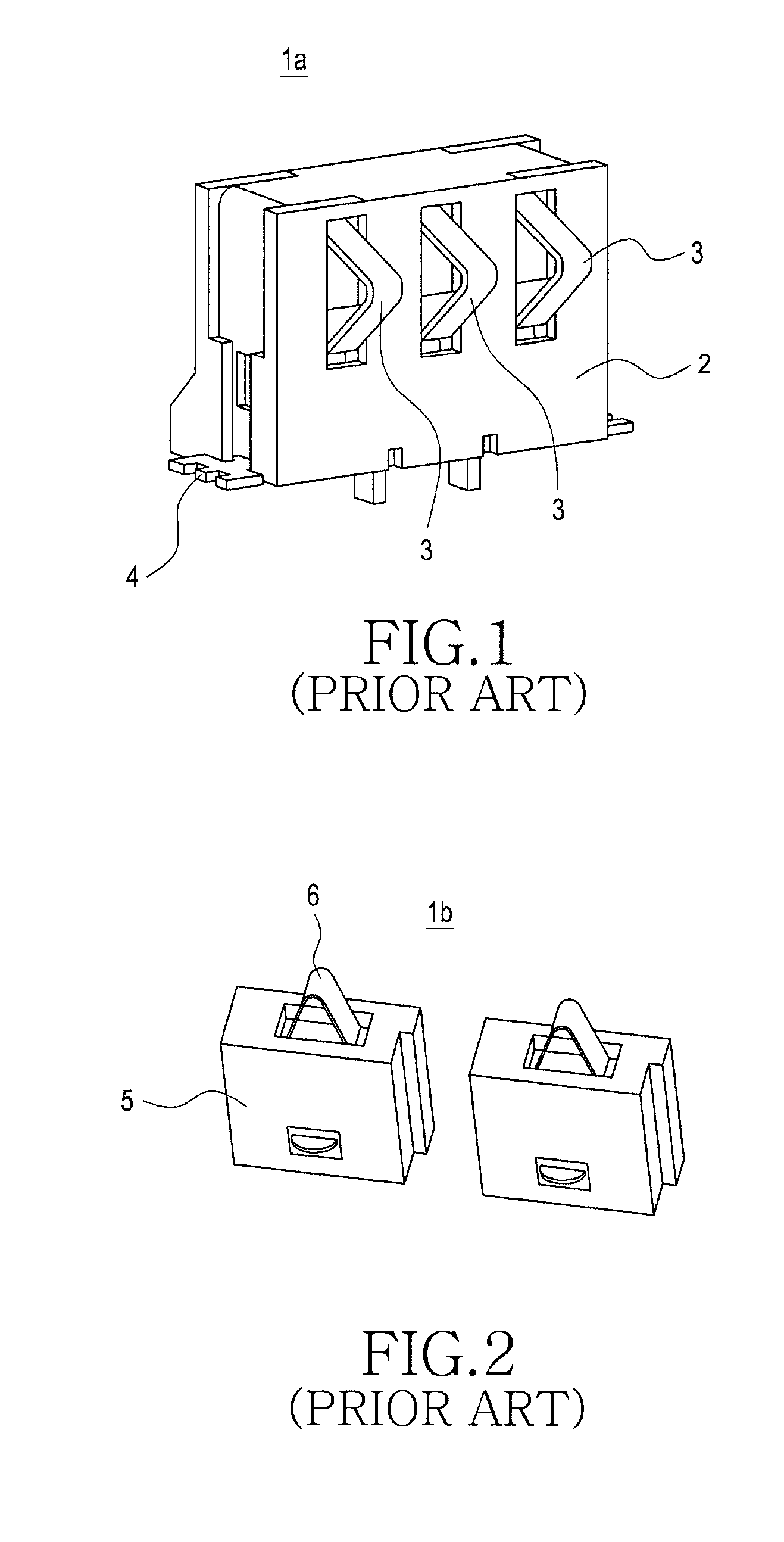
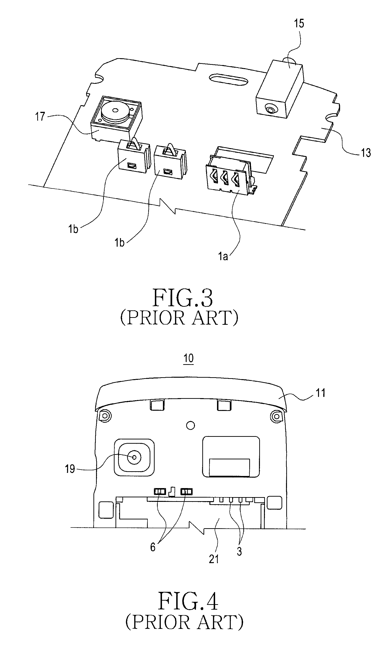
However, since the conventional contact nodes installed in the main board need to be connected to a battery pack, an auxiliary power supply cannot be provided without using preinstalled interface terminals.
This requires the addition of a portable terminal assembling process, increasing material costs and thus increasing a product price.
Also, there is a limit in miniaturizing a portable terminal due to a need to secure a space for installing an auxiliary power supply contact node.

Method used


Image

  • Contact node of portable terminal
  • Contact node of portable terminal
  • Contact node of portable terminal

Examples


Embodiment Construction

[0033]Hereinafter, exemplary embodiments of the present invention will be described in detail with reference to the accompanying drawings. For the purposes of clarity and simplicity, a detailed description of known functions and configurations incorporated herein will be omitted as it may make the subject matter of the present invention rather unclear.

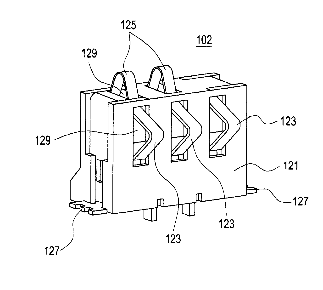
[0034]FIG. 5 is a perspective view illustrating a contact node 102 of a portable terminal 100 (see FIG. 7) according to an embodiment of the present invention. As illustrated in FIG. 5, the contact node 102 of a portable terminal 100 according to the embodiment of the present invention includes a body 121, and first and second contact pieces 123 and 125. The first or second contact pieces 123 or 125 are disposed toward the outside of the portable terminal 100.

[0035]The body 121 is made of a synthetic resin, and includes slots 129 through which the first and second contact pieces 123 and 125 protrude. In addition, fixing pieces 127 are ...


PUM


Abstract

A contact node of a portable terminal includes: a body fixed on a main board of the portable terminal; at least one first contact piece protruding through one side surface of the body; and at least one second contact piece protruding through another side surface of the body, wherein one of the first contact piece and second contact piece is disposed toward an outer side surface of the portable terminal.

Description

CLAIM OF PRIORITY[0001]This application claims the priority under 35 U.S.C. §119 of an application entitled “Contact Node Of Portable Terminal” filed in the Korean Intellectual Property Office on Dec. 16, 2010 and assigned Serial No. 10-2010-0128955, the contents of which are hereby incorporated by reference.BACKGROUND OF THE INVENTION[0002]1. Field of the Invention[0003]The present invention relates to a portable terminal, and more particularly to a contact node of a portable terminal.[0004]2. Description of the Related Art[0005]In general, a portable terminal refers to an electronic device that allows multiple functions including voice communication and message transmission, storage of various information, and a multimedia service such as a game and a video. Such a portable terminal includes various types of devices including an electronic notebook, a palm personal computer, a portable gaming device, a video / music file player, a cellular phone, a laptop computer.[0006]Such a porta...

Claims


Application Information

Patent Timeline
Patent Type & Authority Patents(United States)
IPC IPC(8): H01R12/00H01R12/70H01R31/02
CPCH01R12/7076H01R31/02
Inventor KIM, YUN-SIK
Owner SAMSUNG ELECTRONICS CO LTD
Learn More