Installation structure of sensor and projector apparatus having the same

a technology of installation structure and projector, which is applied in the direction of instruments, liquid/fluent solid measurement, volume/mass flow by differential pressure, etc., can solve the problems of the conventional projector apparatus' mechanism, and achieve the effect of preventing air turbulen

Active Publication Date: 2012-10-16
SANYO ELECTRIC CO LTD
View PDF7 Cites 1 Cited by
  • Summary
  • Abstract
  • Description
  • Claims
  • Application Information

AI Technical Summary

Benefits of technology

[0021]According to the installation structure of the sensor of the present invention, since the buffering unit is disposed downstream of the flow of the air suctioned through the through hole of the sensor so as to communicate with the through hole, turbulence occurring in the flow of the air having passed through the through hole should occur within the buffering unit. Consequently, turbulence of the air can be prevented from extending into the through hole, thus allowing the flow rate or the flow velocity of the air to be reliably sensed.

Problems solved by technology

The cooling mechanism of the conventional projector apparatus, however, poses the following problems.

Method used


Image

  • Installation structure of sensor and projector apparatus having the same
  • Installation structure of sensor and projector apparatus having the same
  • Installation structure of sensor and projector apparatus having the same

Examples


Embodiment Construction

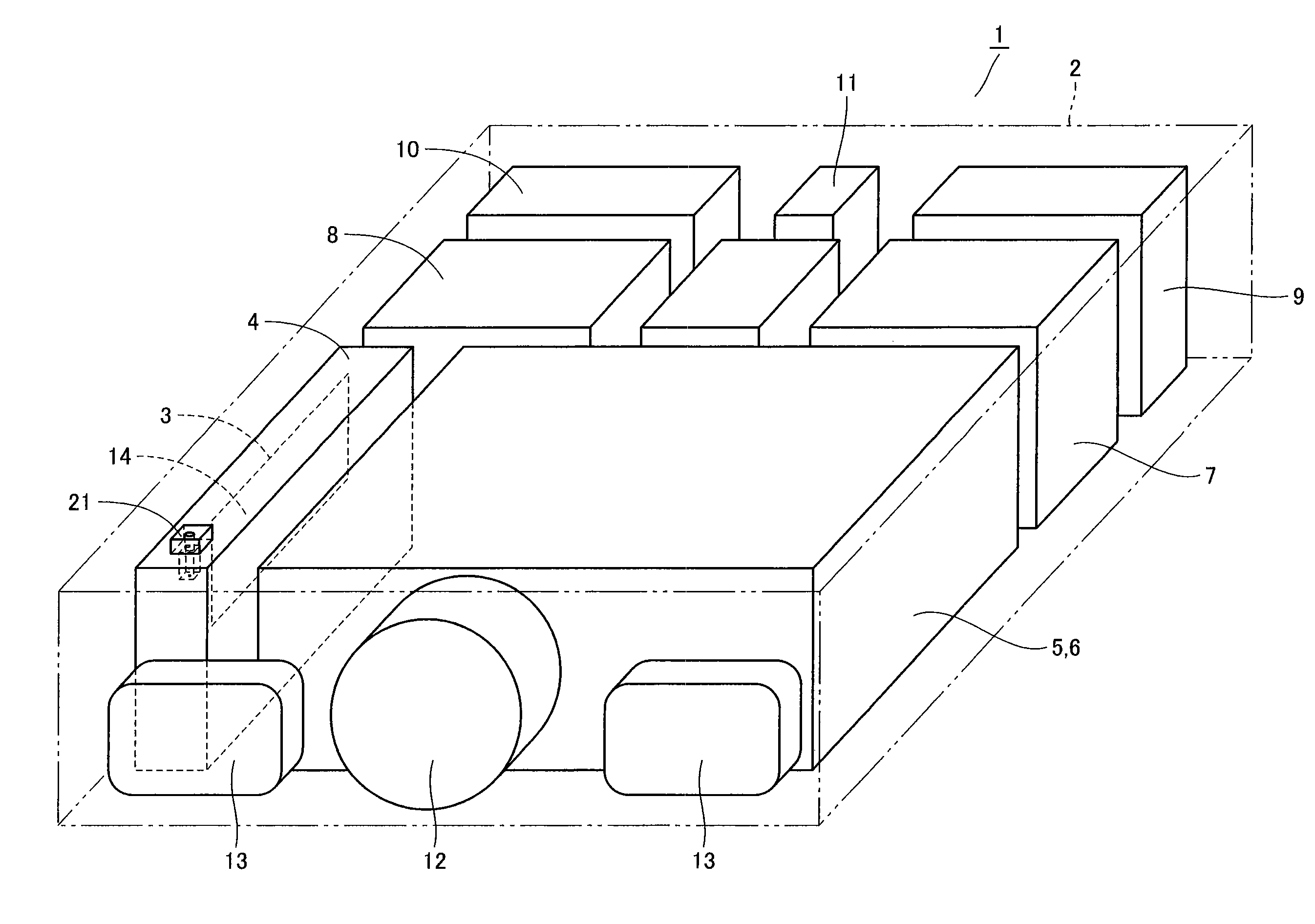
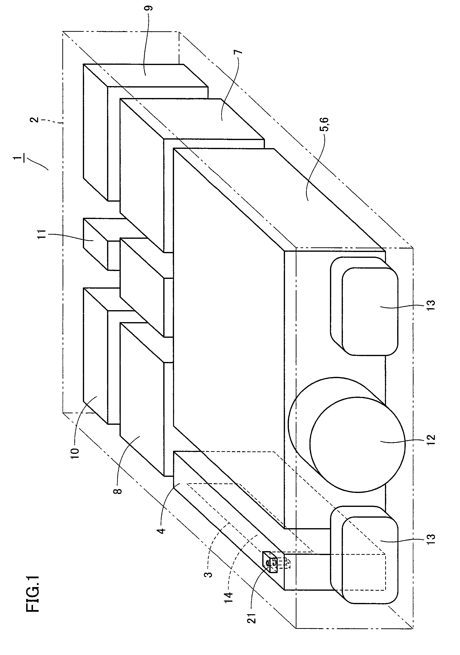
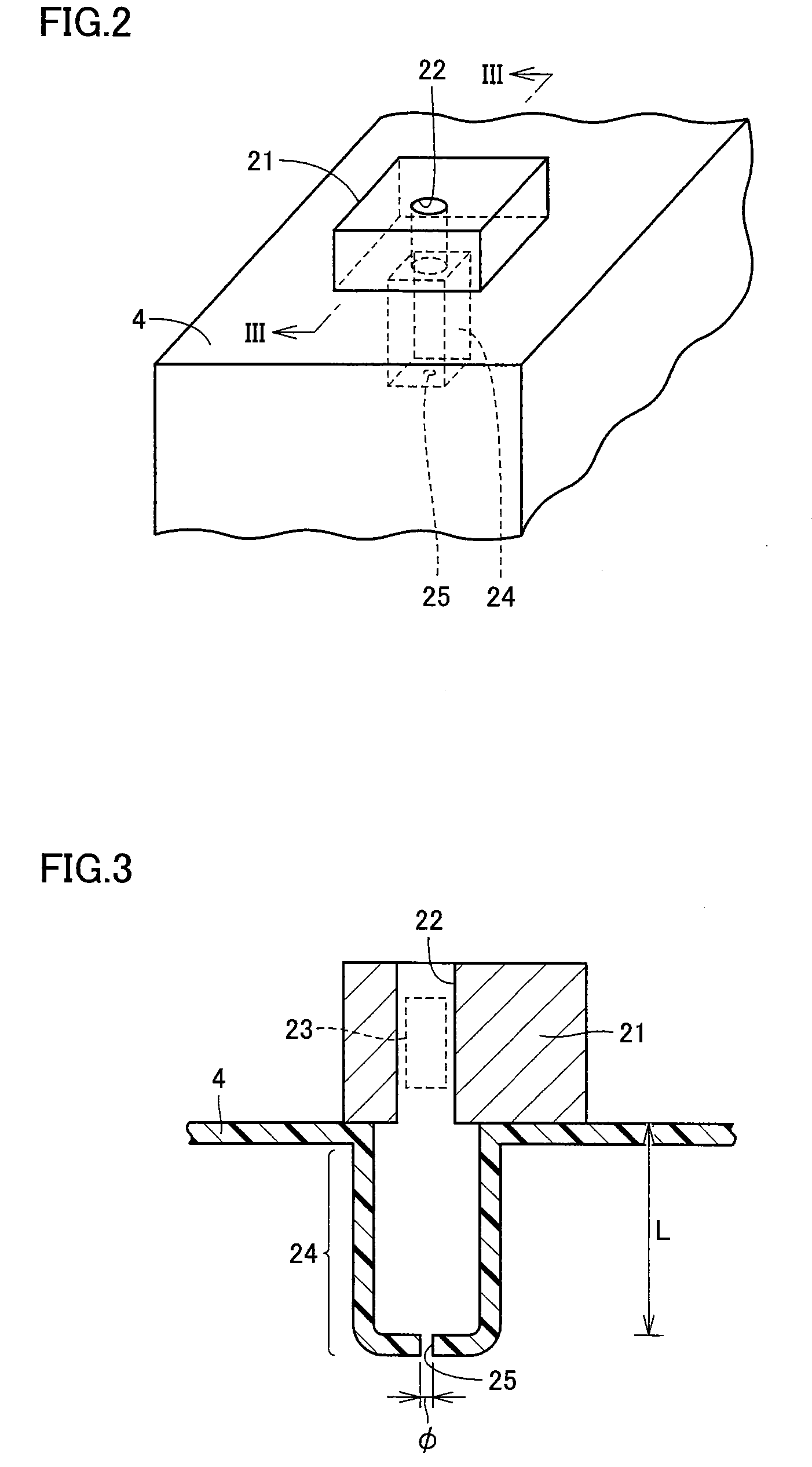
[0034]A projector apparatus employing an installation structure of a sensor according to an embodiment of the present invention will be hereinafter described. As shown in FIG. 1, a projector apparatus 1 has a casing 2 which includes therein an optical system unit 5 for generating color image light; a projection lens 12 for projecting an image; a speaker 13 for audio output; a first lamp unit 7 and a second lamp unit 8 each serving as a light source of optical system unit 5; a control circuit board unit 6 for controlling a series of operations of optical system unit 5, and the like. It is to be noted that one of first lamp unit 7 and second lamp unit 8 is assumed to be a spare lamp unit.

[0035]Furthermore, a first fan 9 and a second fan 10 for introducing the outside air (air) into casing 2 to air-cool the inside of casing 2, and a third fan 11 for actively supplying the air within casing 2 into first (second) lamp units 7 and 8 are disposed in casing 2 as a cooling mechanism for cool...


PUM


Abstract

An airflow rate sensor is provided with a through hole, and a detection unit is disposed inside the through hole. The airflow rate is calculated based on the output voltage resulting from the temperature difference and the like caused in the detection unit by the air flowing through the through hole. A duct is provided with a concave portion so as to protrude from outside the duct toward the inside thereof. The airflow rate sensor is disposed in the duct so as to cover the concave portion, in which the through hole is in communication with the space in the concave portion. The concave portion has a bottom provided with an opening. Accordingly, an installation structure of a sensor for reliably sensing a flow rate and a projector apparatus having the same are provided.

Description

BACKGROUND OF THE INVENTION[0001]1. Field of the Invention[0002]The present invention relates to an installation structure of a sensor and a projector apparatus having the same, and particularly to an installation structure of a sensor for detecting an airflow rate and an air velocity by sensing the flow of the air suctioned due to the differential pressure, and a projector apparatus to which the installation structure of the sensor is applied.[0003]2. Description of the Background Art[0004]In the projector apparatus, the light emitted from a light source is guided by an optical system to produce an image which is then enlarged and projected onto the screen located toward the front thereof. An example of this projector apparatus will be hereinafter described. As shown in FIG. 7, a projector apparatus 101 has a casing 102 which includes therein an optical system unit 105 for generating an image, a first lamp unit 107 and a second lamp unit 108 each serving as a light source, a contro...

Claims


Application Information

Patent Timeline
Patent Type & Authority Patents(United States)
IPC IPC(8): G03B21/16G01F1/34
CPCG01F1/363G01F1/40G03B21/16
Inventor KANBARA, TOSHIMASAYOSHIMURA, TAICHI
Owner SANYO ELECTRIC CO LTD
Why Eureka
Try Eureka