Cyclone separation device and air purification device

A technology of cyclone separation device and gas purification device, which is applied in the direction of suction filter, cleaning equipment, vacuum cleaner, etc., can solve the problems of complex structure, poor separation effect, and many parts, and achieve the effect of simple equipment and avoiding air flow disorder

Pending Publication Date: 2018-11-30
GREE ELECTRIC APPLIANCES INC
View PDF17 Cites 0 Cited by
  • Summary
  • Abstract
  • Description
  • Claims
  • Application Information

AI Technical Summary

Problems solved by technology

[0003] Patent CN105246385A discloses a cyclone separation device, such as figure 1 As shown, it includes a cyclone chamber 5, a collection chamber 6, a guide member 8 and an intermediate exhaust pipe. The front end enters the guide surface, and then enters the collection chamber 6 from the tail end. The structure of the separation device is simple, but the characteristic is that the rotating air flow is close to the exhaust pipe in the middle, which makes it easy for dust to be separated during the cyclone separation process because it is too close to the exhaust pipe. And directly discharged, the separation effect is poor
[0004] Patent CN101816537B discloses a cyclone separation device, such as figure 2 As shown, it includes an upstream cyclone separation device 2 and a downstream cyclone separation assembly 8 arranged around the central axis 16 of the cyclone separation device, and the downstream cyclone separation assembly 8 includes several cyclones 9 connected in parallel to each other, which are jointly constructed The bent whirlwind air duct realizes multi-stage separation of dust and gas, thereby effectively solving the defect of poor separation effect existing in CN105246385A
The cyclone separator described here is a combination of multiple parts to form the primary and secondary separation chambers. The disadvantage is that there are many parts and the structure is complicated.

Method used


Image

  • Cyclone separation device and air purification device
  • Cyclone separation device and air purification device
  • Cyclone separation device and air purification device

Examples


Embodiment 1

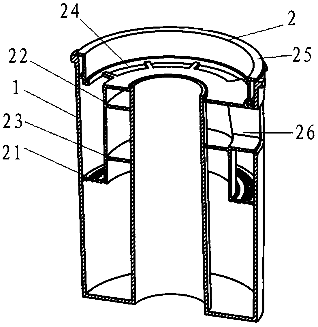
[0041] Figure 3 to Figure 5 As shown, a kind of cyclone separation device provided for the present embodiment comprises:

[0042] The cup body 1 is provided with a cup body air inlet 11 on the side wall, and a cup inner tube 12 is formed upward at the bottom;

[0043] Separator 2, a through hole is formed in the middle to cooperate with the inner tube 12 of the cup, so that the separator 2 can be detachably arranged inside the cup body 1. In this embodiment, the through hole is socketed On the inner tube 12 of the cup, in order to ensure that there is no gap at the junction of the separator 2 and the inner tube 12 of the cup, the two are assembled using an interference fit relationship, and the side wall of the separator 2 and the cup body 1 should also be satisfied. The inner side walls are in seamless contact or form a closed space. In this embodiment, the upper edge of the outer wall of the separator 2 is provided with positioning ribs 25 extending away from the longitudi...

Embodiment 2

[0054] This embodiment provides a gas purification device, specifically a vacuum cleaner, comprising:

[0055] The cyclone separation device described in Embodiment 1 above also has the technical advantages it possesses.


PUM


Abstract

The invention provides a cyclone separation device, and further provides an air purification device. The cyclone separation device comprises a cup body and a separator, and a cup body inner tube is upwards formed at the bottom of the cup body. An upper guide vane and a lower guide vane which are parallel to each other and spiral downwards are formed on the inner side wall of the separator, a firstguide passage is formed between the separator and the inner wall of the cup body, and the inner side wall of the separator, the outer side wall of the cup body inner tube and the upper guide vane andthe lower guide vane together form a second guide passage. Secondary separation of dust-containing airflow is realized by arranging the first guide passage and the second guide passage, a better separation effect on dust air is achieved, the cyclone separation device only includes one cup body and one separator, the cup body and the separator are connected together in a sleeving mode, and the structure is simple and compact.

Description

technical field [0001] The invention relates to the technical field of vacuum cleaners, in particular to a cyclone separation device and a gas purification device. Background technique [0002] The dust cup vacuum cleaner is loved and used by more and more people because the dust cup can be used repeatedly, which is different from the dust bag type that requires frequent replacement of the dust bag. The separator in the existing vacuum cleaner mostly adopts the cyclone type secondary separation, the air containing impurities enters the dust cup along the tangential direction, and during the rotation process from top to bottom, the density of large particles and heavier impurities is greater than that of air, so Due to the large centrifugal force, it collides with the inner wall of the first-stage separator and loses inertia and falls into the lower dust collection chamber to be separated from the air. The finer impurities and air enter the second-stage separator, and the fin...

Claims


Application Information

Patent Timeline
Patent Type & Authority Applications(China)
IPC IPC(8): A47L9/16
CPCA47L9/1608
Inventor 王德旭廖泓斌陈勇任敏陈闪毅黄月林李吉
Owner GREE ELECTRIC APPLIANCES INC
Why Eureka
Try Eureka