Image recording apparatus and image recording method

a recording apparatus and image technology, applied in the direction of printing, other printing apparatus, etc., can solve the problems of affecting the ejection of ink, deteriorating the nozzle, permanent disturbance of recorded images, etc., and achieve the effect of reducing the density unevenness of recorded images caused by such a detected recording element and effectively preventing disturbance of recorded images

Active Publication Date: 2012-10-23
FUJIFILM CORP
View PDF4 Cites 8 Cited by
  • Summary
  • Abstract
  • Description
  • Claims
  • Application Information

AI Technical Summary

Benefits of technology

[0010]The invention of the present application has been contrived with the foregoing in view and it is an object thereof to provide an image recording apparatus and an image recording method that can effectively reduce density unevenness of the recorded image caused by variation in ejection performance of recording elements.

Problems solved by technology

In an image recording apparatus such as inkjet recording apparatus equipped with a plurality of nozzles, variation occurs in ejection characteristics among the nozzles with the passage of time because the ink dries in the nozzle opening, thereby producing deteriorated nozzles in which ejection of ink is adversely affected or non-ejecting nozzles that cannot eject the ink at all.
The presence of such deteriorated nozzles and non-ejecting nozzles leads to permanent disturbance of recorded images, such as white streaks, and is therefore undesirable.
However, the range of levels of density unevenness caused by deterioration of nozzle ejection performance is wide, and in some cases, it is actually extremely difficult to cope with density unevenness by using only the usual shading correction processing with respect to deteriorated nozzles that have lost the capability of ejecting the original ink density (ink amount).
However, density unevenness caused by the presence of such an abnormal density nozzle is not appropriately improved even by the density-increasing density processing (shading correction processing) that increases the amount of ink ejected from the abnormal density nozzle.
As a result, the disturbance of image quality cannot be sufficiently prevented.
However, in the usual inkjet recording apparatus, a limitation is placed on the types and number of inks that can be used.

Method used


Image

  • Image recording apparatus and image recording method
  • Image recording apparatus and image recording method
  • Image recording apparatus and image recording method

Examples


Embodiment Construction

[0051]An embodiment of the present invention will be described below with reference to the appended drawings.

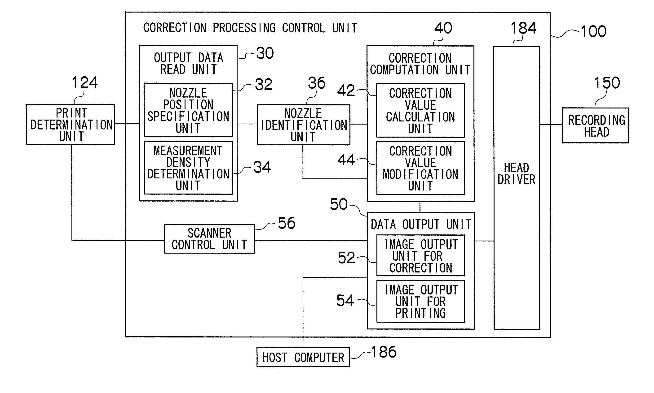
[0052]First, the ink ejection correction performed during image recording in an inkjet recording apparatus equipped with a plurality of nozzles will be explained and then the configuration of the inkjet recording apparatus will be described. In the embodiment described hereinbelow, the case is illustrated by way of example in which the present invention is applied to an inkjet recording apparatus in which a desired image is formed on a recording medium by ejecting ink from a recording head having a plurality of nozzles, but the present invention is not limited to the inkjet recording apparatus.

Nozzle Ejection Performance

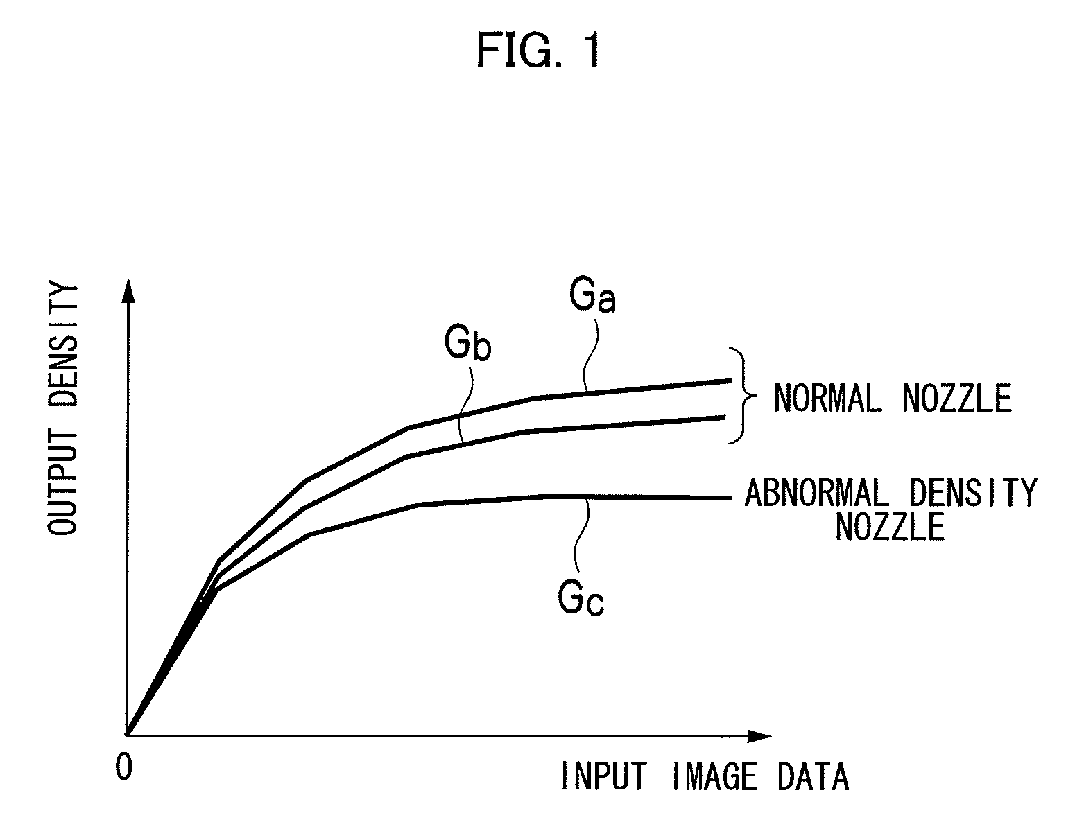
[0053]FIG. 1 shows the relationship between input image data (input density data) inputted for ejecting ink from a nozzle and an output density (output density data) of an ink dot formed on the recording medium. In FIG. 1, input image data based on tone values...


PUM


Abstract

An image recording apparatus includes: a recording head having a plurality of recording elements; a conveying device; a density information acquisition device; a characteristic computation device; a characteristic storage device; a comparison device which compares recording information with stored characteristic information; a density correction value calculation device which calculates a correction value for recording control according to the comparison result; a density correction value modification device which performs modification of the correction value; and an image correction device which corrects data of an image outputted by the plurality of recording elements according to the correction value calculated by the density correction value calculation device and the correction value modified by the density correction value modification device.

Description

BACKGROUND OF THE INVENTION[0001]1. Field of the Invention[0002]The present invention relates to an image recording apparatus and an image recording method, and more particularly to an image recording apparatus and an image recording method that correct density unevenness caused by variation in characteristics of recording elements when an image is recorded on a recording medium by using a recording head including a plurality of recording elements.[0003]2. Description of the Related Art[0004]In an image recording apparatus such as inkjet recording apparatus equipped with a plurality of nozzles, variation occurs in ejection characteristics among the nozzles with the passage of time because the ink dries in the nozzle opening, thereby producing deteriorated nozzles in which ejection of ink is adversely affected or non-ejecting nozzles that cannot eject the ink at all. The presence of such deteriorated nozzles and non-ejecting nozzles leads to permanent disturbance of recorded images, ...

Claims


Application Information

Patent Timeline
Patent Type & Authority Patents(United States)
IPC IPC(8): B41J29/393
CPCB41J2/2139
Inventor SASAYAMA, HIROYUKI
Owner FUJIFILM CORP
Why Eureka
Try Eureka