Bipolar or ultrasonic surgical device

a surgical device and ultrasonic technology, applied in the direction of surgical staples, surgical forceps, therapy, etc., can solve the problems of affecting the coagulation of tissue, and affecting the coagulation speed of tissue, so as to reduce the number of staples and less mechanical force

Active Publication Date: 2012-10-23
TYCO HEALTHCARE GRP LP
View PDF274 Cites 1803 Cited by
  • Summary
  • Abstract
  • Description
  • Claims
  • Application Information

AI Technical Summary

Benefits of technology

[0015]In further example embodiments and / or example methods of the present invention, there may be a reduced number of staples and thus less mechanical force to form staples and transect tissue. Further, example embodiments and / or example methods may use bipolar radio-frequency (RF) energy and / or staples to coagulate and cut tissue. Further, example embodiments and / or example methods may include one row of staples or no staples. Further, example embodiments may include an energy surgical attachment (DLU) which consists of two opposing jaws where the two opposing jaws may include, e.g., one or two, rows of bipolar electrical contacts.

Problems solved by technology

Several of the bipolar surgical instruments may encounter problems with the application of the heat of the tissue.
Adjacent tissue may be damaged due to application of excessive heat.
Conversely, where less energy is applied to the electrodes in order to prevent over heating, the coagulation of the tissue may require more time than desired.
Due to the cutting and stapling functions, many of these mechanical surgical instruments require an excessive amount of force in order to effectively perform their functions.

Method used


Image

  • Bipolar or ultrasonic surgical device
  • Bipolar or ultrasonic surgical device
  • Bipolar or ultrasonic surgical device

Examples


Embodiment Construction

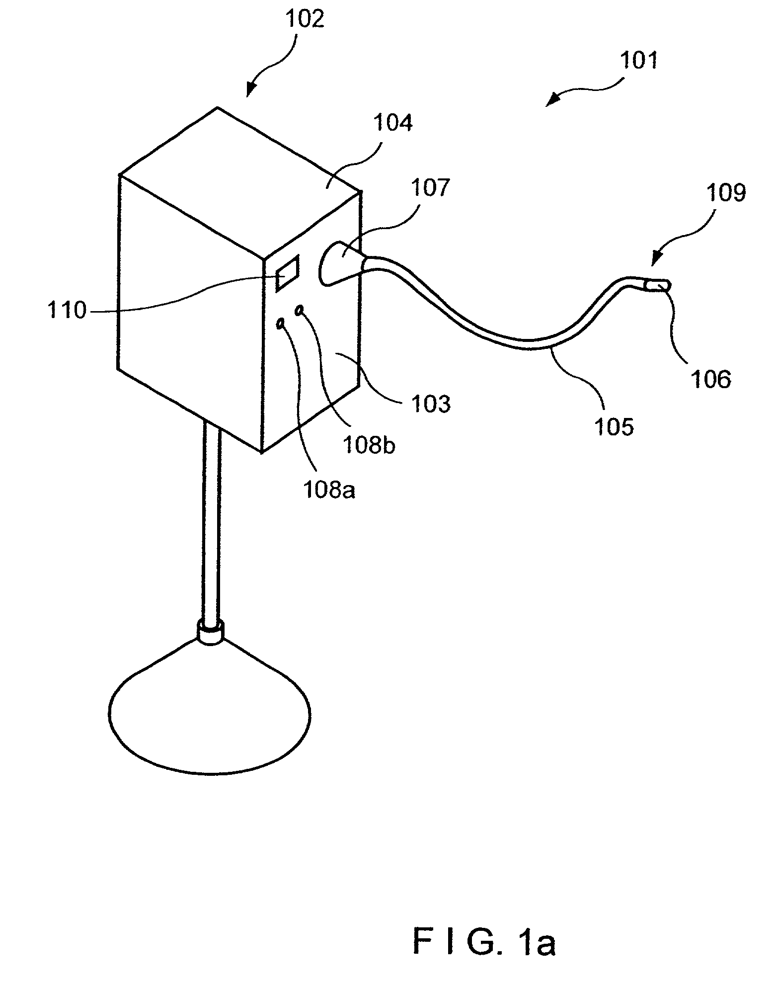
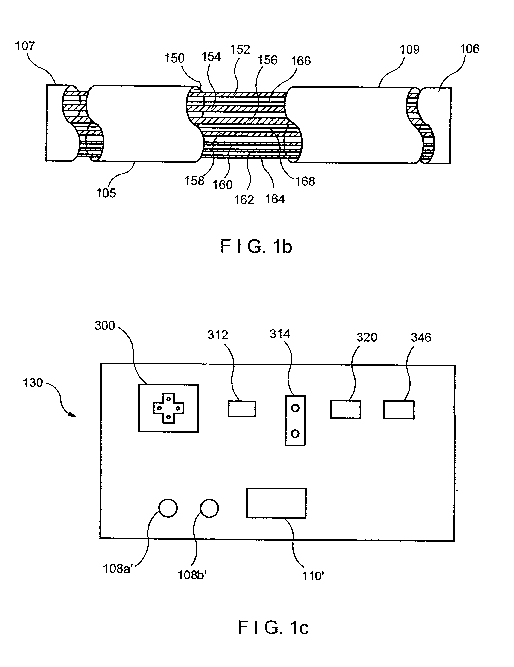
[0050]Referring to FIG. 1a, a perspective view of an electro-mechanical driver device 101 according to one example embodiment of the present invention is illustrated. Such an electro-mechanical driver device is described in, for example, U.S. patent application Ser. No. 09 / 723,715, entitled “Electro-Mechanical Surgical Device,” which is expressly incorporated herein in its entirety by reference thereto. Electro-mechanical driver device 101 may include, for example, a remote power console 102, which includes a housing 104 having a front panel 103. Mounted on front panel 103 are a display device 106 and indicators 108a and 108b. A flexible shaft 105 may extend from housing 104 and may be detachably secured thereto via a first coupling 107. The distal end 109 of flexible shaft 105 may include a second coupling 106 adapted to detachably secure a surgical instrument or attachment to the distal end 109 of the flexible shaft 105. In accordance with the example embodiment of the present inv...


PUM


Abstract

An electro-mechanical surgical device, system and/or method may include a housing, at least two opposing jaw, and at least one electrical contact associated with at least one of the jaws. The electrical contact may include at least one of a bipolar electrical contact and an ultrasonic electrical contact. The electrical contact may be a row of electrodes located on one or all of the jaws. A sensor may also be associated with any tissue located between the jaws to sense and report the temperature of that tissue. A piercable ampulla containing fluid may also be placed on at least one of the jaws so that the fluid is releasable when the jaws are in closed position and the electrode(s) pass through the tissue into the piercable ampulla.

Description

CROSS-REFERENCES TO RELATED APPLICATIONS[0001]This application claims the benefit of U.S. Provisional Patent Application Ser. No. 60 / 285,113, filed on Apr. 20, 2001, and of U.S. Provisional Patent Application Ser. No. 60 / 289,370, filed on May 8, 2001, each of which is expressly incorporated herein in is entirety by reference thereto.[0002]This application also expressly incorporates in its entirety by reference thereto International Published Patent Application No. WO 00 / 72765. This application also expressly incorporates in its entirety by reference thereto U.S. patent application Ser. No. 09 / 723,715, filed on Nov. 28, 2000, which is a continuation-in-part of U.S. patent application Ser. No. 09 / 324,451, filed on Jun. 2, 1999, now U.S. Pat. No. 6,315,184, issued on Nov. 13, 2001, a continuation-in-part of U.S. patent application Ser. No. 09 / 324,452, filed on Jun. 2, 1999, a continuation-in-part of U.S. patent application Ser. No. 09 / 351,534, filed on Jul. 12, 1999, now U.S. Pat. No....

Claims


Application Information

Patent Timeline
Patent Type & Authority Patents(United States)
IPC IPC(8): A61B18/14A61B17/3201A61B17/28A61B17/32A61B18/00A61B18/12A61N7/02
CPCA61B17/320068A61B17/320092A61B18/1442A61B17/068A61N7/02A61B5/01A61B5/4836A61B17/07207A61B17/285A61B18/1477A61B2018/145A61B2019/448A61B2018/1425A61B90/98A61B2017/320069A61B2017/320071A61B2017/320094A61B2017/320095A61B2017/320097
Inventor WHITMAN, MICHAEL P.
Owner TYCO HEALTHCARE GRP LP
Why Eureka
Try Eureka