
Brush gear of a motor

a brush and gear technology, applied in the field of electric motors, can solve the problems of not always possible or desirable, affecting the appearance and appearance of the brush, and the remaining brush must carry a greater curren

Inactive Publication Date: 2012-10-23
JOHNSON ELECTRIC SA
View PDF14 Cites 8 Cited by
  • Summary
  • Abstract
  • Description
  • Claims
  • Application Information

AI Technical Summary

Benefits of technology

[0006]Preferably, the wire has a soldered tip at each end thereof, and when the tip extends through the hole, solder is scraped off from the tip and retained between the fingers and the wire to increase the electrical contact area between the finger and the corresponding wire.

Problems solved by technology

However, this means that the remaining brushes must carry greater current and this is not always possible or desirable.
This is considered unsightly and clumsy.
This is a good solution but requires a relatively large brush card and an expensive insert molding process.
However, welding inside the brush card is difficult and prevents miniaturization due to the area required to make a good weld connection.

Method used


Image

  • Brush gear of a motor
  • Brush gear of a motor
  • Brush gear of a motor

Examples


Embodiment Construction

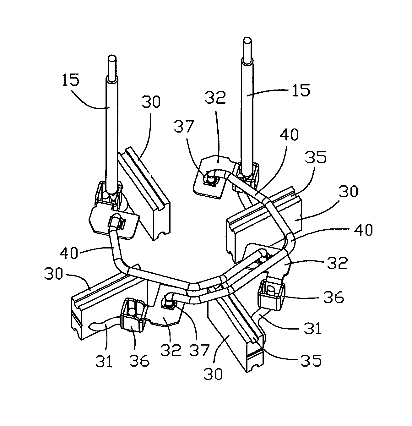
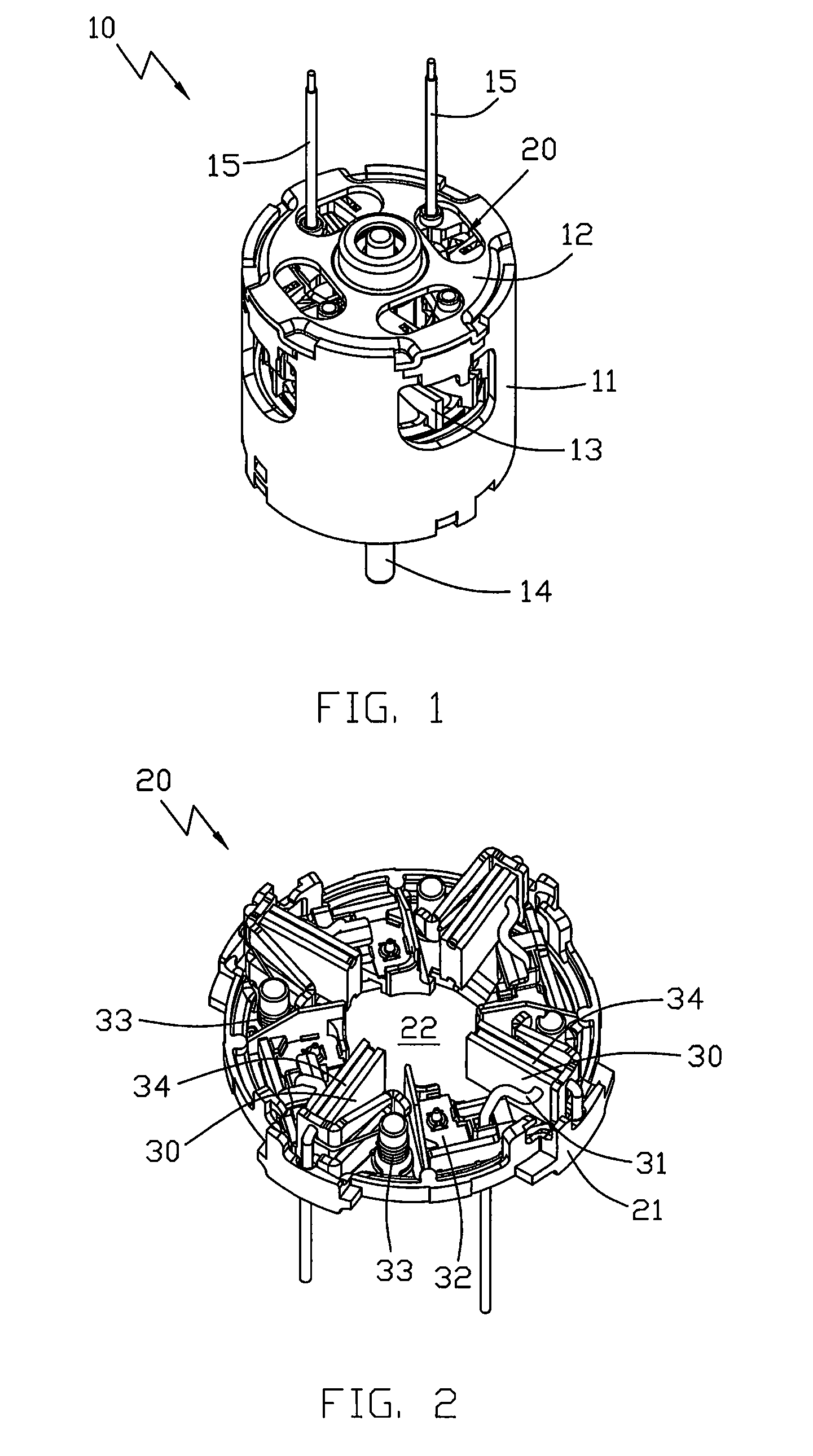
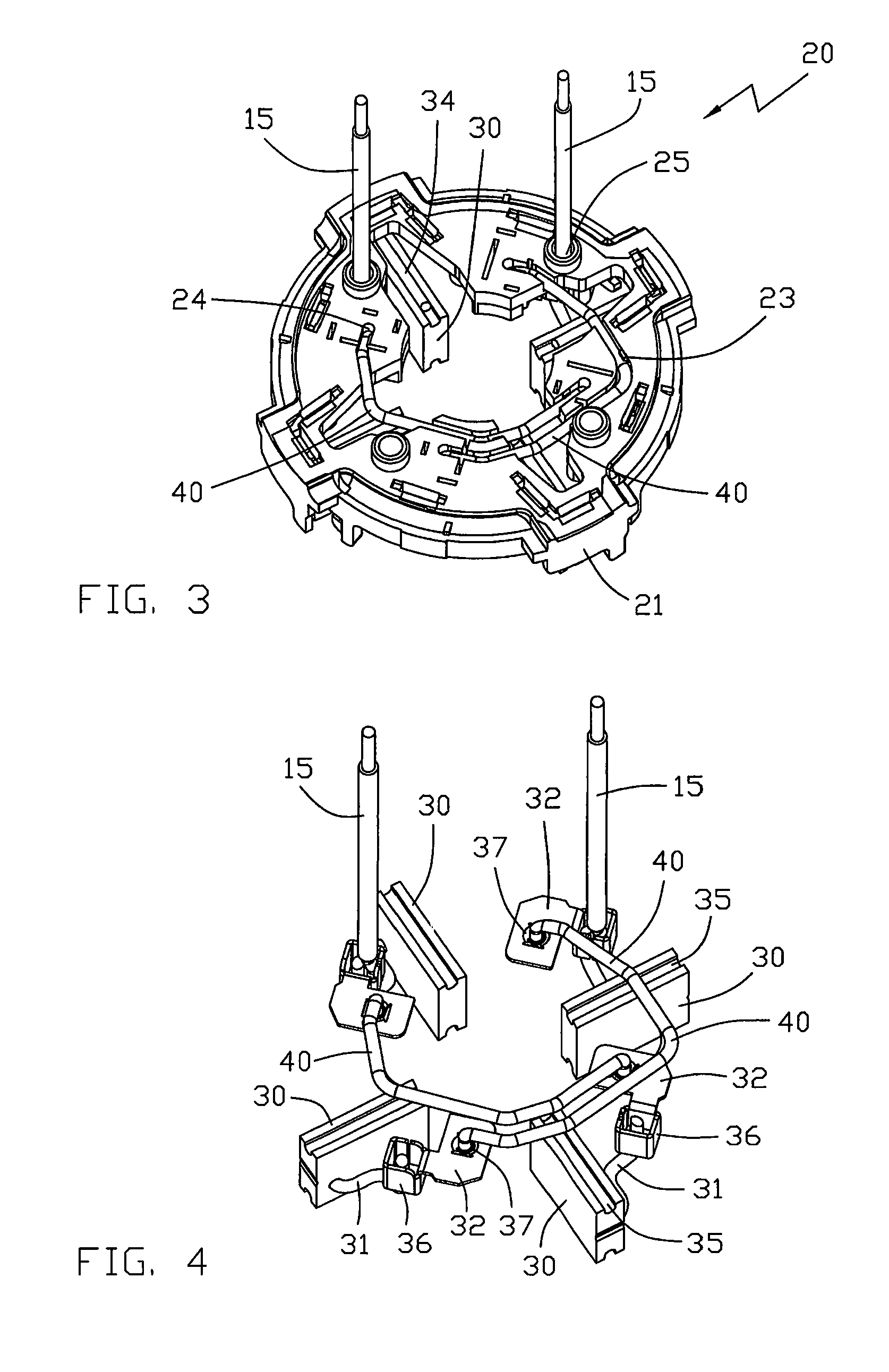
[0024]FIG. 1 illustrates a multi-pole PMDC motor 10 in accordance with the present invention. PMDC stands for permanent magnet direct current and the motor has a permanent magnet stator comprising an magnetic housing accommodating either separate permanent magnet pieces or a single magnet formed into a ring and magnetized to form a number of magnetic poles. Multi-pole refers to a motor having four or more stator poles. The illustrated motor has four stator poles for simplicity of description but the invention is applicable to motors with more than four stator poles.

[0025]The motor has an end cap 12 closing one end of the housing 11 and a rotor 13 disposed within the housing 11. The rotor has a shaft 14 which is journalled in bearings. The rotor is a wound rotor having a rotor core and a commutator fitted to the shaft and rotor windings wound about the rotor core and connected to the commutator. A fan may be fixed to the rotor for cooling the motor. Motor terminations 15, illustrated...


PUM


Abstract

Brush gear of a motor has a brush card with a plurality of brushes installed at one side thereof. Each brush is electrically connected with a connector. Two motor terminations provide power to the brushes via the corresponding connectors and at least one wire connects two of the connectors. Each of said two of the connectors has a hole to receive one end of the wire and at least two fingers extends from an edge of the hole inclined toward the axis of the hole, such that when the end of the wire extends through the hole, the fingers are resiliently deformed and grip the wire to prevent withdrawal of the wire from the hole.

Description

CROSS REFERENCE TO RELATED APPLICATIONS[0001]This non-provisional patent application claims priority under 35 U.S.C. §119(a) from Patent Application No. 200810141965.7 filed in The People's Republic of China on Aug. 22, 2008.FIELD OF THE INVENTION[0002]This invention relates to an electric motor and in particular, to brush gear of a motor.BACKGROUND OF THE INVENTION[0003]For electric motors, especially PMDC motors, with 4 or more stator poles, it is usual to have the same number of brushes as stator poles, cooperating with a commutator to energize the rotor windings in the correct sequence. The brushes are divided into two groups with all the brushes within each group being electrically connected together. Some recent improvements in motor design use equalizers or electrical connections to join together various segments of the commutator, such as diametrically opposed segments for a four pole motor, to reduce the number of brush sets. However, this means that the remaining brushes m...

Claims


Application Information

Patent Timeline
Patent Type & Authority Patents(United States)
IPC IPC(8): H02K13/00
CPCH01R39/383H02K5/148H01R4/48
Inventor LAU, JAMES CHING SIKWONG, DUNCAN YIU LUNGJIN, CHANG LINLIU, ALOYS J.
Owner JOHNSON ELECTRIC SA
Learn More