Split type polar plate lap joint structure and electrolytic bath with same

A connection structure, split technology, applied in the direction of electrolysis process, electrolysis components, electrodes, etc., can solve the problems of long electrolysis time, large contact resistance, virtual contact, etc., to improve the electrical contact area, the average distance between cathode and anode, and the cell voltage low effect

Inactive Publication Date: 2017-02-22
HANGZHOU EMPEROR LOSSEN TECH
View PDF7 Cites 0 Cited by
  • Summary
  • Abstract
  • Description
  • Claims
  • Application Information

AI Technical Summary

Problems solved by technology

[0002] At present, domestic and international manufacturers adopting electrolysis process technology, all their processes adopt parallel connection of cathode and anode, each cathode and anode have only one contact, and the contact between the conductive beam of cathode and anode plate and the contact of copper busbar basically adopts surface contact and point contact. The method of contact has its disadvantages 1. Due to the relatively long electrolysis time, the surface of the copper busbar is easily oxidized and the acid mist on site is relatively large, which may easily cause the acid mist to float to the lap joint, resulting in an increasing contact resistance and contact Poor virtual contact phenomenon occurs, resulting in uneven current between cathode and anode, which seriously affects production quality, physical appearance, and poor electrical efficiency.
Disadvantage 2. The anode and cathode plates are freely overlapped by the weight of the plate, and the weight of the plate will affect the conductive effect. The weight of the plate is heavy, and the conductive effect is good. There is a certain buoyancy in the electrolyte, which often causes false contact and virtual contact, which has a great impact on the energy consumption of electrolysis and increases the work intensity of electrolytic cell surface management, which brings great benefits to further enhance international and domestic high-current production. limit

Method used


Image

  • Split type polar plate lap joint structure and electrolytic bath with same
  • Split type polar plate lap joint structure and electrolytic bath with same
  • Split type polar plate lap joint structure and electrolytic bath with same

Examples


Embodiment 1

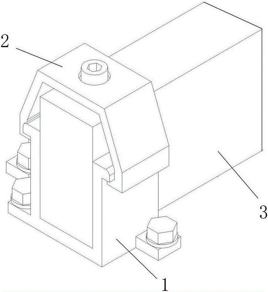
[0036] Figure 1-5 Schematically shows a split-type electrode plate overlapping structure according to an embodiment of the present invention. Such as Figure 5 shown, including:

[0037] At least two conductive busbars 7 arranged in parallel (the number is set according to needs);

[0038] The conductive beam fixing seat 4 and the limit seat 5 arranged on the conductive busbar 7 and located at both ends of the conductive beam 3 (each conductive beam 3 is located between two adjacent conductive busbars 7), the same The conductive beam fixing seat 4 and the limit seat 5 on the conductive busbar 7 are arranged at intervals;

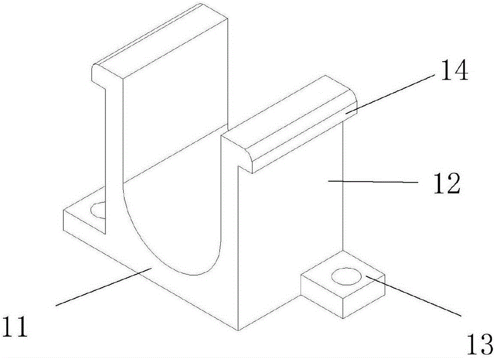
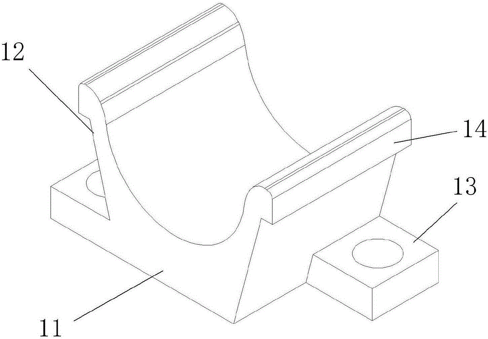
[0039] The conductive beam fixing seat 4 includes: a seat body 1, made of conductive material, having a bottom edge 11 of the seat body, two side edges 12 of the seat body and an opening at the top;

[0040] The position limiting seat 5 is made of insulating material, has a base body bottom 11 and two seat body side edges 12 and has an open top.

[004...

Embodiment 2

[0054] This embodiment provides an electrolytic cell, such as Figure 8 and 9 , including a rectangular tank 9 with an open top, two long sides of the tank 9 are provided with a split-type plate lap joint structure as described in Embodiment 1, and the split-type pole plate lap joint structure is fixed and arranged in the slot The conductive beam 3 on the body 9, and the electrode 8 (cathode or anode) protruding into the tank body 9 under the conductive beam 3 .

[0055] When multiple slot bodies 9 are arranged side by side, the adjacent sides of two adjacent slot bodies 9 can share one conductive bus bar 7 .

[0056] The electrolytic cell of this embodiment has the split-type electrode plate overlapping structure of Embodiment 1, and therefore also has the advantages described in Embodiment 1.

[0057] Such as Figure 9 The cathode and the anode of the electrodes 8 are arranged at intervals, and the conductive beam fixing seat 4 and the limit seat 5 in the same row are als...


PUM


Abstract

The invention discloses a split type polar plate lap joint structure which comprises a conductive bus bar, a conductive beam fixing seat and a limit seat, wherein the conductive beam fixing seat comprises a seat body and a cover body, the seat body is made from a conductive material and provided with a seat body bottom edge and two seat body side edges, and an opening is formed in the top; the cover body is made from an insulation material, the top of the seat body is covered with the cover body, and the cover body is provided with a cover body top surface and two cover body side edges; the limit seat is made from an insulation material and provided with a seat body bottom edge and two seat body side edges, and an opening is formed in the top. By the aid of the arrangement of the conductive beam fixing seat, the cover body applies pressure to a conductive beam from the top, and the conductive beam is accommodated in the seat body, so that the conductive beam is surrounded by the four surfaces of the conductive beam fixing seat, the electrical contact area of the conductive bus bar and the conductive beam is increased, the contact of the conductive beam and the conductive bus bar is good, the bath voltage is lower, the cathode and anode spaces are uniform and no error exists, the electric efficiency is higher, the conductive beam and a polar plate cannot be loosened along with human factors and electrolysis technology factors after the conductive beam is pressed by the cover body, and the false contact phenomenon cannot be caused.

Description

technical field [0001] The invention relates to the technical field of electrolysis equipment, in particular to a split-type polar plate overlapping structure and an electrolytic cell with the structure. Background technique [0002] At present, domestic and international manufacturers adopting electrolysis process technology, all their processes adopt parallel connection of cathode and anode, each cathode and anode have only one contact, and the contact between the conductive beam of cathode and anode plate and the contact of copper busbar basically adopts surface contact and point contact. The method of contact has its disadvantages 1. Due to the relatively long electrolysis time, the surface of the copper busbar is easily oxidized and the acid mist on site is relatively large, which may easily cause the acid mist to float to the lap joint, resulting in an increasing contact resistance and contact Bad virtual contact occurs, resulting in uneven current between the cathode ...

Claims


Application Information

Patent Timeline
Patent Type & Authority Applications(China)
IPC IPC(8): C25C7/02C25C7/00
CPCC25C7/02C25C7/00
Inventor 林建洪
Owner HANGZHOU EMPEROR LOSSEN TECH
Why Eureka
Try Eureka