
Contactor for realizing electric connection between moving and stationary contact poles in transformer

A technology of dynamic and static contacts and electrical connection, which is applied in the field of electricity, can solve the problems of unreliable electrical connection, etc., and achieve the effect of increasing the electrical contact area and tight and firm fit

Inactive Publication Date: 2011-06-29
SHANGHAI RITCHEY ELECTRICAL EQUIP
View PDF0 Cites 0 Cited by
  • Summary
  • Abstract
  • Description
  • Claims
  • Application Information

AI Technical Summary

Problems solved by technology

[0002] In the prior art, the cable connector used to connect the transformer is composed of a medium and high voltage insulating bushing, a static contact rod, a moving contact rod and an American cable joint, wherein the connection between the static contact rod and the moving contact rod The end face contact method requires that there is no gap between the two opposite end faces of the static contact rod and the moving contact rod, but affected by the assembly process and environmental pressure, Unreliable electrical connection between

Method used


Image

  • Contactor for realizing electric connection between moving and stationary contact poles in transformer
  • Contactor for realizing electric connection between moving and stationary contact poles in transformer
  • Contactor for realizing electric connection between moving and stationary contact poles in transformer

Examples


Embodiment Construction

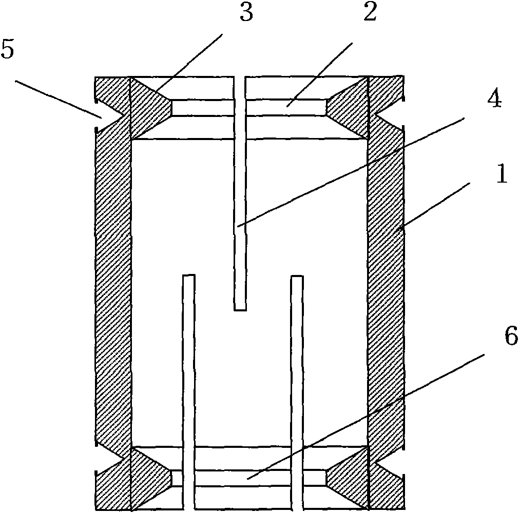
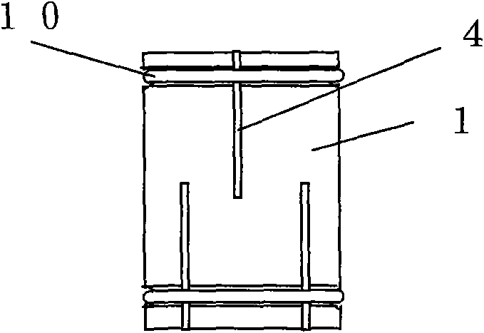
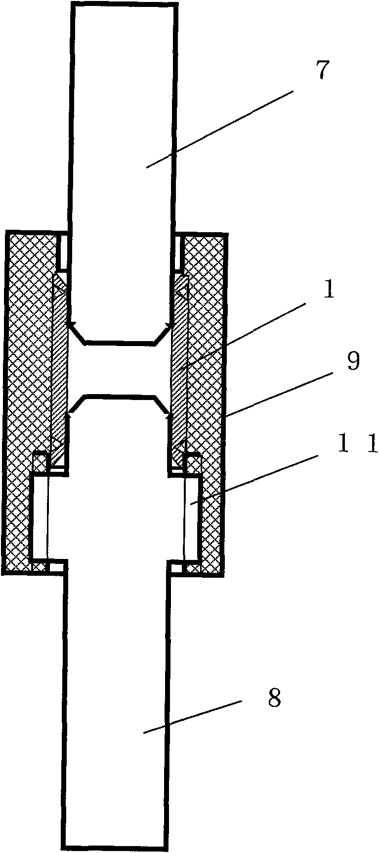
[0015] Such as figure 1 and figure 2 As shown, the contactor of the present invention for realizing the electrical connection of the moving and static contact rods in the transformer is composed of a cylindrical metal tube 1, wherein an annular ring is arranged on the inner peripheral wall of one end of the cylindrical metal tube 1 toward the axial direction. Flange 2, the connecting surface 3 between the annular flange 2 and the end surface of the cylindrical metal pipe 1 is a conical surface, the inner diameter of the annular flange 2 is smaller than the inner diameter of the middle part of the cylindrical metal pipe 1, and the inner diameter of the cylindrical metal pipe 1 There are more than two cracks 4 arranged in the tube wall, the extension direction of any one of the cracks 4 is parallel to the axial direction of the cylindrical metal tube 1, and the cracks 4 start from the cylindrical metal tube 1 where the annular flange 2 is located. One end begins to extend towa...


PUM


Abstract

The invention discloses a contactor for realizing electric connection between moving and stationary contact poles in a transformer, which consists of a cylindrical metal tube, wherein an annular flange is arranged on an inner circumferential wall at one end of the cylindrical metal tube toward the direction of an axial centre; a connection surface between the annular flange and an end face of the cylindrical metal tube is a conical surface; more than two cracks are arranged in a tube wall of the cylindrical metal tube; the extending direction of any one of the cracks is parallel to the axial direction of the cylindrical metal tube; the cracks extend to the cylindrical metal tube from one end of the cylindrical metal tube where the annular flange is located; an annular groove is arranged on an outer circumferential wall of the end of the cylindrical metal tube where the annular flange is located; and a reinforcing clamping spring is sleeved in the annular groove. In the use of the contactor for realizing the electric connection between the moving and stationary contact poles in the transformer, the electric connection between an inner circumferential surface of the cylindrical metal tube and outer circumferential surfaces of the stationary and moving contact poles is realized, so that electric contact area is increased greatly and tight and firm connection between the annular flange and the conical surface thereof and between the stationary contact pole and an internal thread sleeve is realized.

Description

technical field [0001] The invention relates to the electrical field, in particular to a cable connector, in particular to a contactor for realizing the electrical connection of a moving and static contact rod in a transformer. Background technique [0002] In the prior art, the cable connector used to connect the transformer is composed of a medium and high voltage insulating bushing, a static contact rod, a moving contact rod and an American cable joint, wherein the connection between the static contact rod and the moving contact rod The end face contact method requires that there is no gap between the two opposite end faces of the static contact rod and the moving contact rod, but affected by the assembly process and environmental pressure, The electrical connection between them is unreliable. Contents of the invention [0003] The object of the present invention is to provide a contactor for realizing the electrical connection of the dynamic and static contact rods in...

Claims


Application Information

Patent Timeline
Patent Type & Authority Applications(China)
IPC IPC(8): H01R4/60H01R11/03H01R4/48H01F27/28
Inventor 徐兴财
Owner SHANGHAI RITCHEY ELECTRICAL EQUIP
Learn More