Axial fan

a technology of axial fans and fan blades, applied in mechanical equipment, engine cooling equipment, liquid fuel engines, etc., can solve problems such as fan operation problems

Active Publication Date: 2012-10-30
SPAL AUTOMOTIVE
View PDF5 Cites 21 Cited by
  • Summary
  • Abstract
  • Description
  • Claims
  • Application Information

AI Technical Summary

Benefits of technology

[0010]One aim of the invention is to provide an improved axial fan which is reliable even when operating in particularly difficult environmental conditions.
[0011]Another aim of the invention is to provide an improved axial fan which is simple and economical to produce.

Problems solved by technology

Axial fans of the type described above have several disadvantages, in particular if used with the cooling circuit of a motorcycle and, especially an off-road motorcycle.
In the most common working conditions for motorcycles it is quite easy for water, sand and soil to build up in the gap between the electric motor and the impeller hub, creating a sludge that may cause problems with fan operation.

Method used


Image

  • Axial fan
  • Axial fan
  • Axial fan

Examples


Embodiment Construction

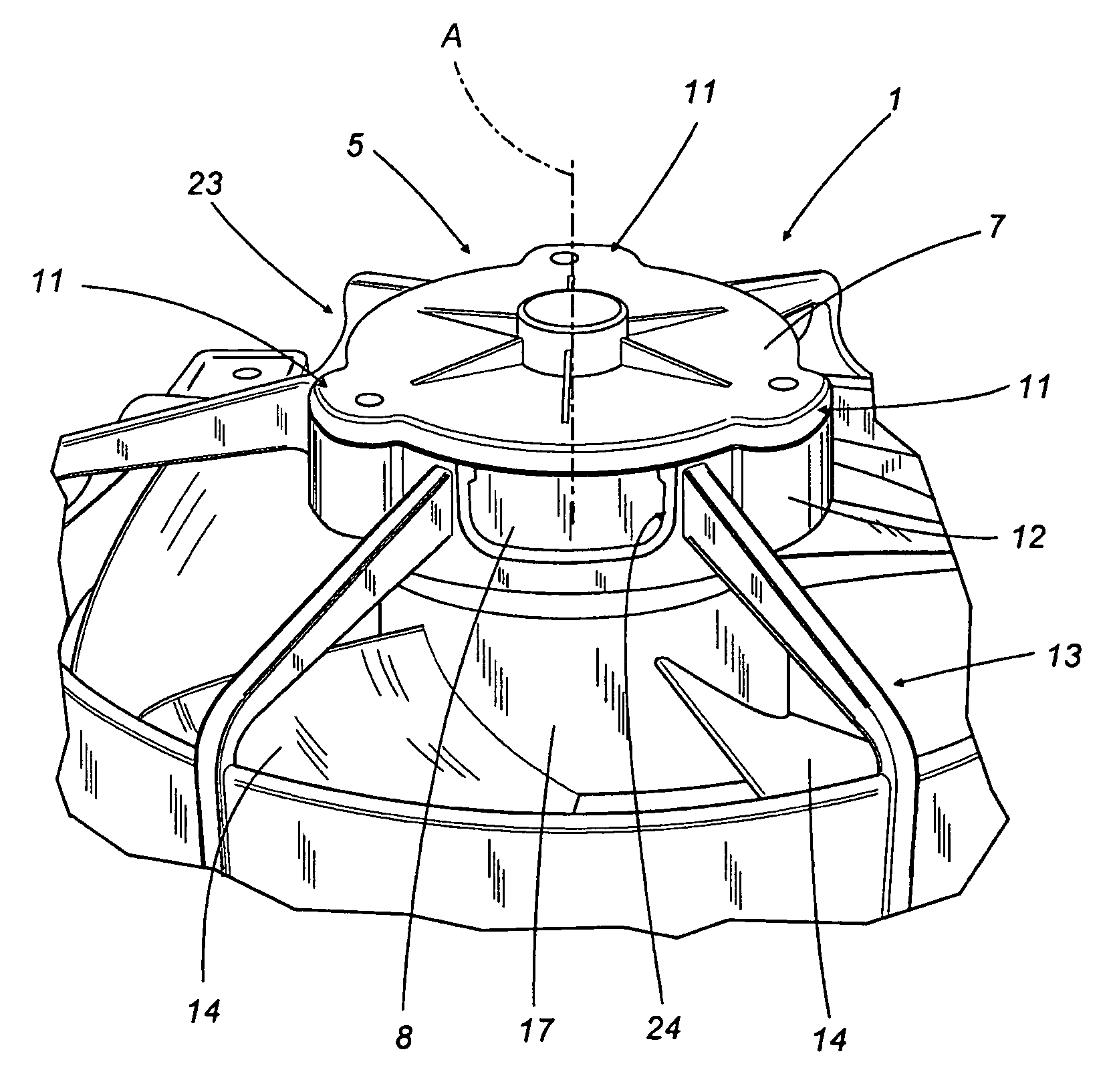
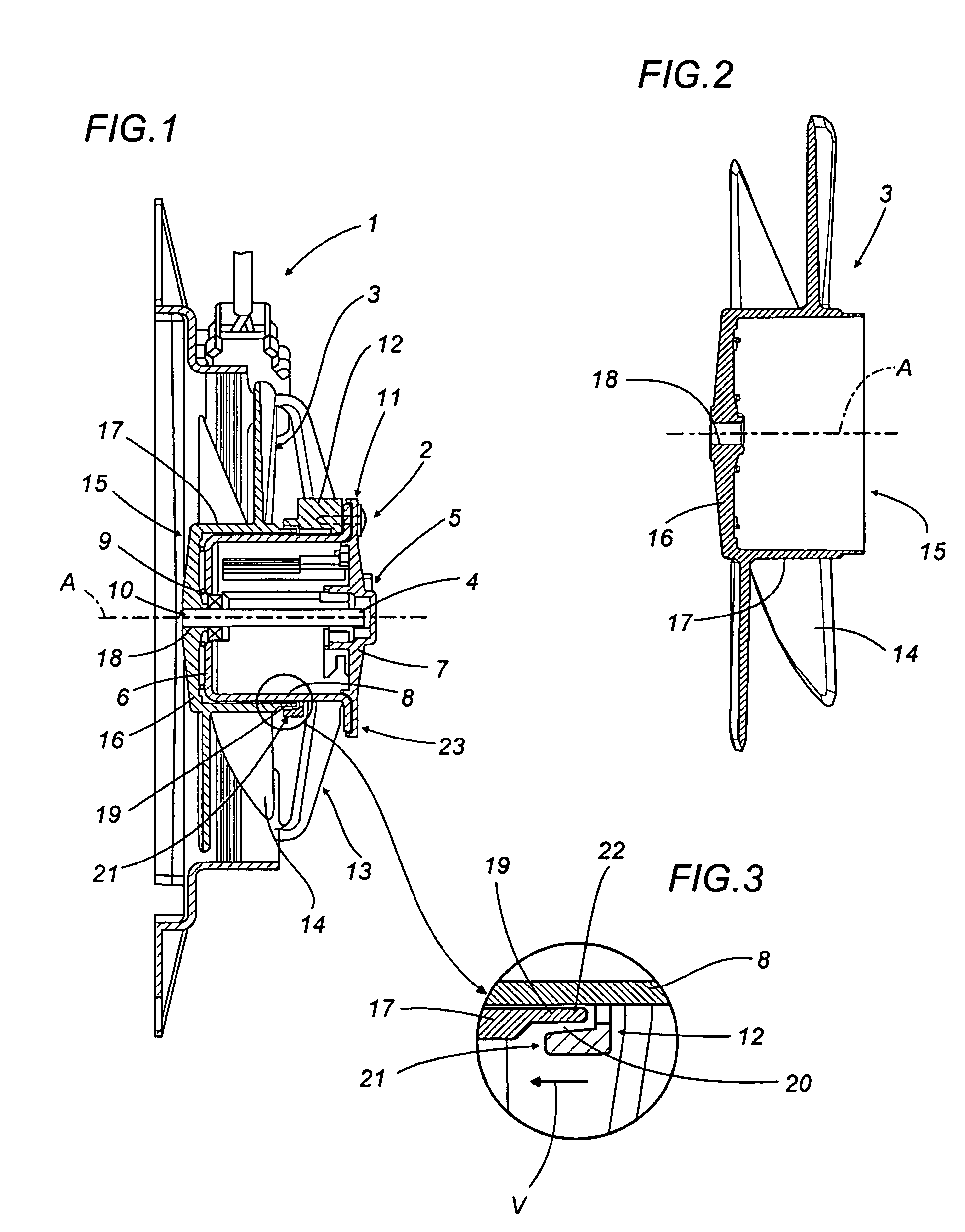
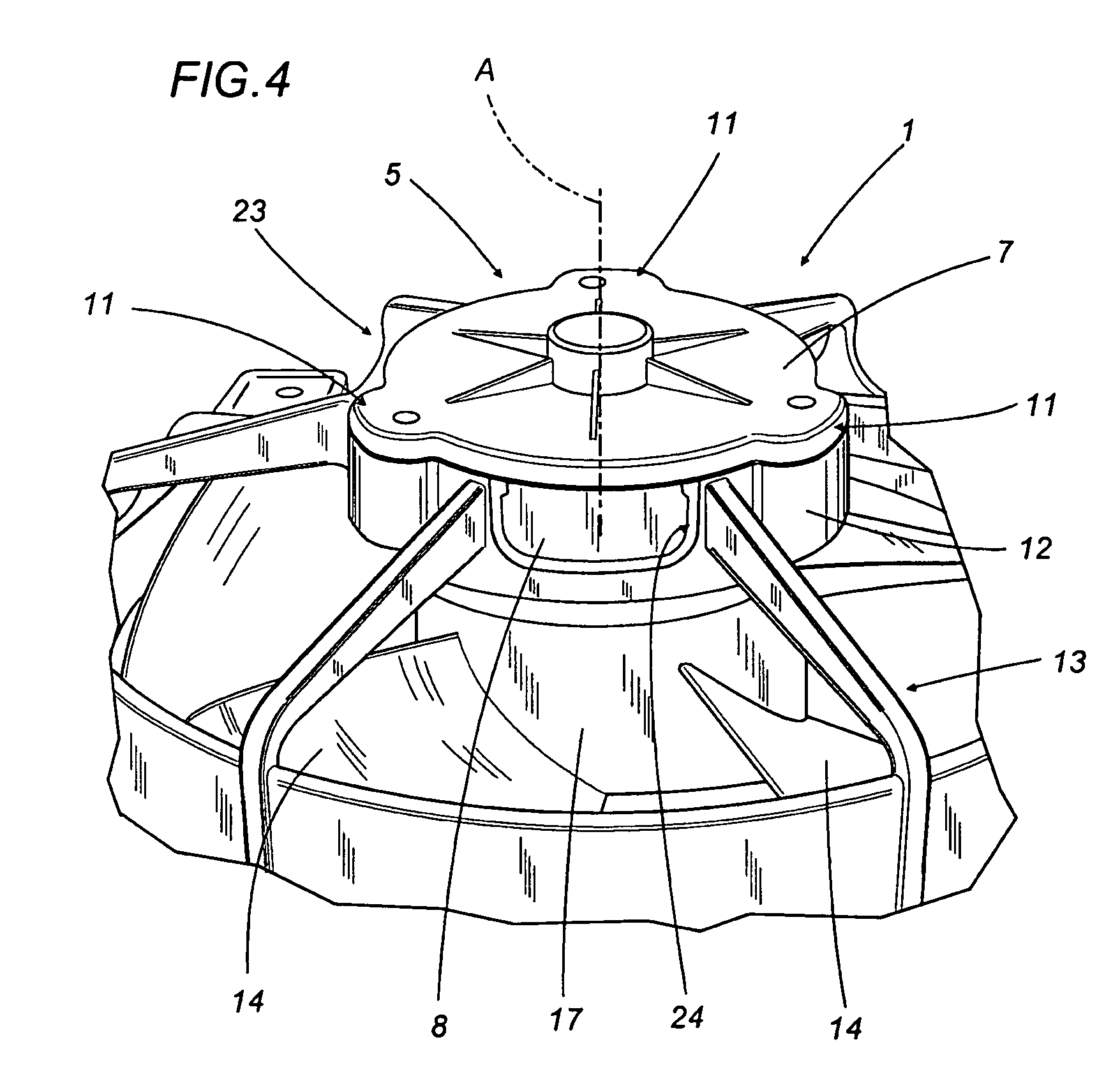
[0023]With reference to FIG. 1, the numeral 1 denotes an axial fan which can be used to particular advantage with a cooling circuit (not illustrated) of an engine of a motorcycle (also not illustrated).

[0024]The fan 1 comprises an electric motor 2 and an impeller 3, rotationally driven about its central axis A by the shaft 4 of the electric motor 2.

[0025]The electric motor 2 comprises a substantially cylindrical protective outer casing 5 with a first end wall 6, a second end wall 7, positioned opposite each other, and an annular side wall 8 extending between the two end walls 6 and 7.

[0026]The end wall 6 has a central hole 9 through which one end 10 of the shaft 4 protrudes, while the end wall 7 is defined by a lid from whose periphery there extend three protrusions 11 spaced at angular intervals of 120° about the axis A.

[0027]As shown in more detail in FIG. 4, the protrusions 11 are fixed to a crown 12 that laterally surrounds and supports the electric motor 2 at a longitudinal end...


PUM


Abstract

In an axial fan (1), equipped with a frame (13), a motor (2) and an impeller (3) whose hub (15) is rotationally driven by the motor (2) and where the hub (15) is cup-shaped, with an end wall (16) and an annular side wall (17) to partially contain the motor (2), the motor (2) protrudes from the hub (15) with its longitudinal end (23) which is supported and laterally surrounded by a crown (12) of the frame (13) and the crown (12) has an annular end strip (21) facing the hub (15) and laterally surrounding an annular end strip (22) of the hub (15) which faces the crown (12).

Description

[0001]This is a National Phase Application filed under 35 U.S.C. 371 as a national stage of PCT / IB2007 / 001781, with the filing date of Jun. 28, 2007, an application claiming the benefit under 35 USC 119(e) of Italian Patent Application BO2006A000652, filed Sep. 21, 2006, the entire content of which is hereby incorporated by reference in its entirety.TECHNICAL FIELD[0002]This invention relates to an axial fan.[0003]The fan according to this invention may advantageously be used in a system for cooling the engine of a motorcycle to which the following description refers, without in any way limiting the scope of the invention.BACKGROUND ART[0004]Generally speaking, an engine cooling system comprises a radiator, which is part of a cooling circuit designed to dissipate into the environment the heat which a liquid circulating inside it carries away from the engine, and an axial fan, which generates a forced air flow through the radiator to promote the latter's dissipation of the heat.[0005...

Claims


Application Information

Patent Timeline
Patent Type & Authority Patents(United States)
IPC IPC(8): F04B35/00
CPCF04D25/0613F04D29/083F04D29/329F04D29/526F01P5/06
Inventor SPAGGIARI, ALESSANDRO
Owner SPAL AUTOMOTIVE
Why Eureka
Try Eureka