Fluid disc pump

a disc pump and fluid technology, applied in the direction of pump control, positive displacement liquid engine, machine/engine, etc., can solve the problems of reduced useful work done by the fluid actuator, reduced pump efficiency, and low amplitude acoustic resonance in the disc-shaped cavity, so as to reduce the dampening of the displacement oscillation, and mitigate any reduction of the pressure oscillation

Active Publication Date: 2012-10-30
TTP VENTUS LTD
View PDF10 Cites 32 Cited by
  • Summary
  • Abstract
  • Description
  • Claims
  • Application Information

AI Technical Summary

Benefits of technology

[0008]According to one embodiment of the invention, the actuator of the pump described above causes an oscillatory motion of the driven end wall (“displacement oscillations”) in a direction substantially perpendicular to the end wall or substantially parallel to the longitudinal axis of the cylindrical cavity, referred to hereinafter as “axial oscillations” of the driven end wall within the cavity. The axial oscillations of the driven end wall generate substantially proportional “pressure oscillations” of fluid within the cavity creating a radial pressure distribution approximating that of a Bessel function of the first kind as described in the '487 Application which is incorporated by reference herein, such oscillations referred to hereinafter as “radial oscillations” of the fluid pressure within the cavity. A portion of the driven end wall between the actuator and the side wall provides an interface with the side wall of the pump that decreases dampening of the displacement oscillations to mitigate any reduction of the pressure oscillations within the cavity, that portion being referred to hereinafter as an “isolator.” The illustrative embodiments of the isolator are operatively associated with the peripheral portion of the driven end wall to reduce dampening of the displacement oscillations.
[0009]According to another embodiment of the invention, a pump comprises a pump body having a substantially cylindrical shape defining a cavity formed by a side wall closed at both ends by substantially circular end walls, at least one of the end walls being a driven end wall having a central portion and a peripheral portion adjacent the side wall, wherein the cavity contains a fluid when in use. The pump further comprises an actuator operatively associated with the central portion of the driven end wall to cause an oscillatory motion of the driven end wall in a direction substantially perpendicular thereto with a maximum amplitude at about the centre of the driven end wall, thereby generating displacement oscillations of the driven end wall when in use. The pump further comprises an isolator operatively associated with the peripheral portion of the driven end wall to reduce dampening of the displacement oscillations caused by the end wall's connection to the side wall of the cavity. The pump further comprises a first aperture disposed at about the centre of one of the end walls, and a second aperture disposed at any other location in the pump body, whereby the displacement oscillations generate radial oscillations of fluid pressure within the cavity of said pump body causing fluid flow through said apertures.

Problems solved by technology

However, high amplitude acoustic resonance has not been employed within disc-shaped cavities in which radial pressure oscillations are excited until recently.
Thus, the useful work done by the actuator on the fluid is reduced and the pump becomes less efficient.

Method used


Image

  • Fluid disc pump
  • Fluid disc pump
  • Fluid disc pump

Examples


Embodiment Construction

[0035]In the following detailed description of several illustrative embodiments, reference is made to the accompanying drawings that form a part hereof: and in which is shown by way of illustration specific preferred embodiments in which the invention may be practiced. These embodiments are described in sufficient detail to enable those skilled in the art to practice the invention, and it is understood that other embodiments may be utilized and that logical structural, mechanical, electrical, and chemical changes may be made without departing from the spirit or scope of the invention. To avoid detail not necessary to enable those skilled in the art to practice the embodiments described herein, the description may omit certain information known to those skilled in the art. The following detailed description is, therefore, not to be taken in a limiting sense, and the scope of the illustrative embodiments are defined only by the appended claims.

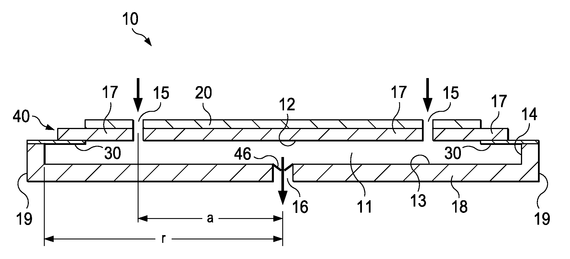
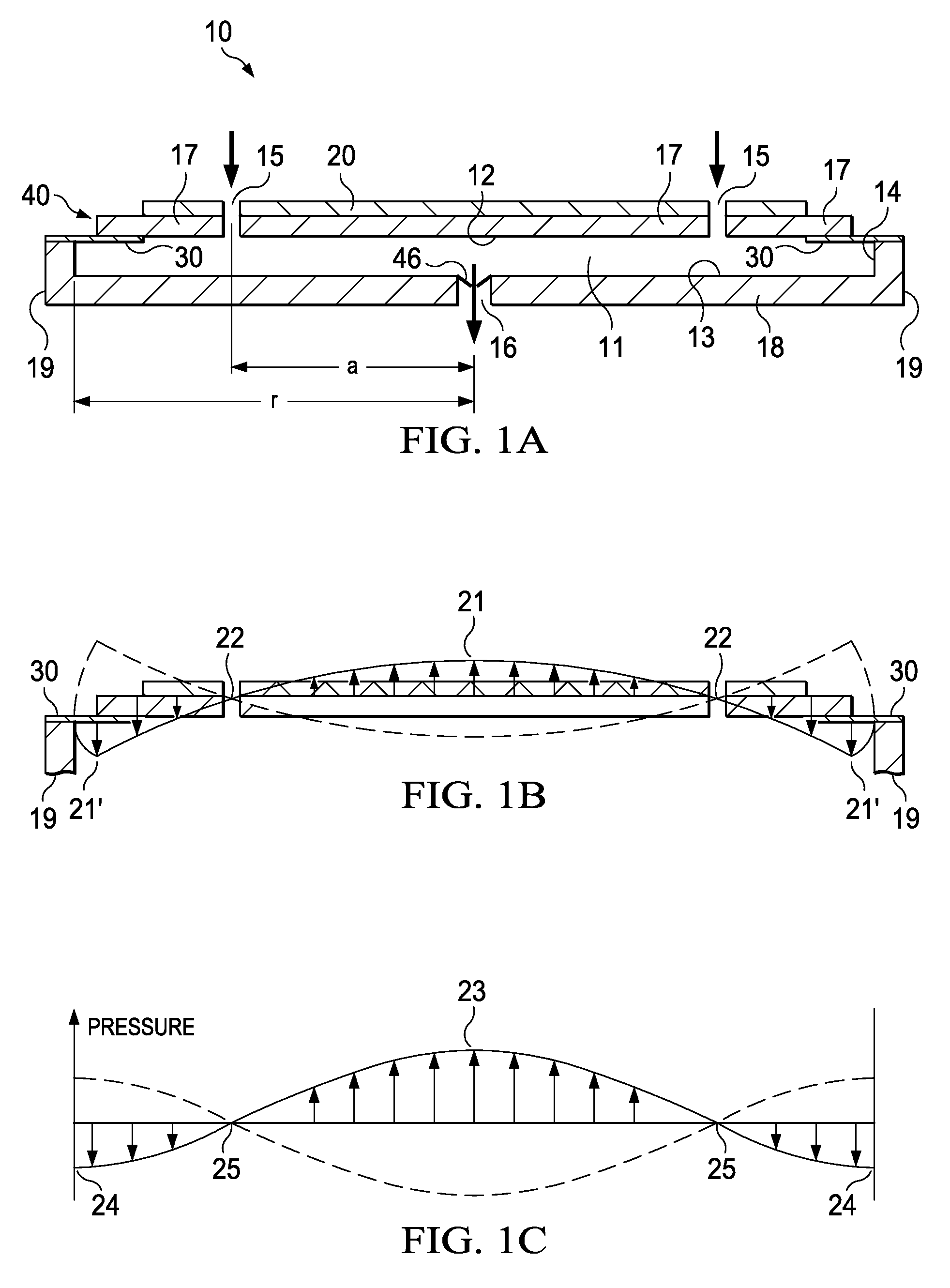
[0036]FIG. 1A is a schematic cross-sectio...


PUM


Abstract

A pump having a substantially cylindrical shape and defining a cavity formed by a side wall closed at both ends by end walls wherein the cavity contains a fluid is disclosed. The pump further comprises an actuator operatively associated with at least one of the end walls to cause an oscillatory motion of the driven end wall to generate displacement oscillations of the driven end wall within the cavity. The pump further comprises an isolator operatively associated with a peripheral portion of the driven end wall to reduce dampening of the displacement oscillations. The pump further comprises a valve for controlling the flow of fluid through the valve. The valve has first and second plates with offsetting apertures and a sidewall disposed between the plates around the perimeter of the plates to form a cavity in fluid communication with the apertures. The valve further comprises a flap disposed and moveable between the first and second plates and having apertures substantially offset from the apertures of one plate and substantially aligned with the apertures of the other plate. The flap is motivated between the two plates in response to a change in direction of the differential pressure of fluid across the valve.

Description

BACKGROUND OF THE INVENTION[0001]1. Field of the Invention[0002]The illustrative embodiments of the invention relate generally to a pump for fluid and, more specifically, to a pump having a substantially disc-shaped cavity with substantially circular end walls and a side wall and a valve for controlling the flow of fluid through the pump.[0003]2. Description of Related Art[0004]The generation of high amplitude pressure oscillations in closed cavities has received significant attention in the fields of thermo-acoustics and pump type compressors. Recent developments in non-linear acoustics have allowed the generation of pressure waves with higher amplitudes than previously thought possible.[0005]It is known to use acoustic resonance to achieve fluid pumping from defined inlets and outlets. This can be achieved using a cylindrical cavity with an acoustic driver at one end, which drives an acoustic standing wave. In such a cylindrical cavity, the acoustic pressure wave has limited ampli...

Claims


Application Information

Patent Timeline
Patent Type & Authority Patents(United States)
IPC IPC(8): F04B17/00
CPCF04B43/04F04F7/00
Inventor VAN RENSBURG, RICHARD JANSEHATFIELD, STUART ANDREWBUCKLAND, JUSTIN RORKEMCCRONE, JAMES EDWARD
Owner TTP VENTUS LTD
Why Eureka
Try Eureka