
Tire pressure monitoring system and pressure monitoring unit

a technology of pressure monitoring system and tire pressure, which is applied in vehicle tyre testing, instruments, roads, etc., to achieve the effect of saving time and effort inherent in wheel replacement and updating current mounting information

Active Publication Date: 2012-10-30
HONDA MOTOR CO LTD
View PDF13 Cites 9 Cited by
  • Summary
  • Abstract
  • Description
  • Claims
  • Application Information

AI Technical Summary

Benefits of technology

The present invention provides a tire pressure monitoring system and a pressure monitoring unit that can save time and effort in replacing a wheel. The system stores an identification code of a tire pressure sensor unit provided with a prepared mounting wheel and a tire-pressure set value as a pair in a pressure monitoring unit. While the vehicle is traveling at a speed equal to or greater than a predetermined vehicle speed, when identification codes in tire-pressure data received within a predetermined time coincide with identification codes stored as the identification codes of prepared mounting wheels and the number of coinciding identification codes is equal to the number of the running wheels of the vehicle, data on a running wheel is updated. The pressure monitoring unit uses various formats of information and can update the current mounting information upon a predetermined condition, such as when an ignition switch is turned on or when the detection value of a centrifugal force sensor becomes equal to or greater than a predetermined value. The system can appropriately update the current running wheel mounting information without transmitting an instruction from the pressure monitoring unit to any of the tire pressure sensor units. The benefit of updating the current mounting information increases.

Problems solved by technology

According to the TPMS disclosed in Japan Patent No. 3815305, when a centrifugal force sensor provided in a pressure sensor of a spare wheel (spare tire) loaded in a local vehicle or of a wheel loaded for replacement is activated due to hard vibration originating from a rough road and the tire pressure sensor unit transmits data on a tire pressure even though such wheel is not mounted as a running wheel, the monitoring unit may wrongly register the sensor ID of that tire pressure sensor unit as the sensor ID of the running wheel.
Moreover, replacement of plural wheels (tire set) such as replacement from wheels of summer tires to wheels of winter tires is not taken into consideration of disclosure of Japan Patent No. 3815305.

Method used


Image

  • Tire pressure monitoring system and pressure monitoring unit
  • Tire pressure monitoring system and pressure monitoring unit
  • Tire pressure monitoring system and pressure monitoring unit

Examples


Embodiment Construction

[0040]An explanation will be given of an embodiment of the present invention with reference to the accompanying drawings.

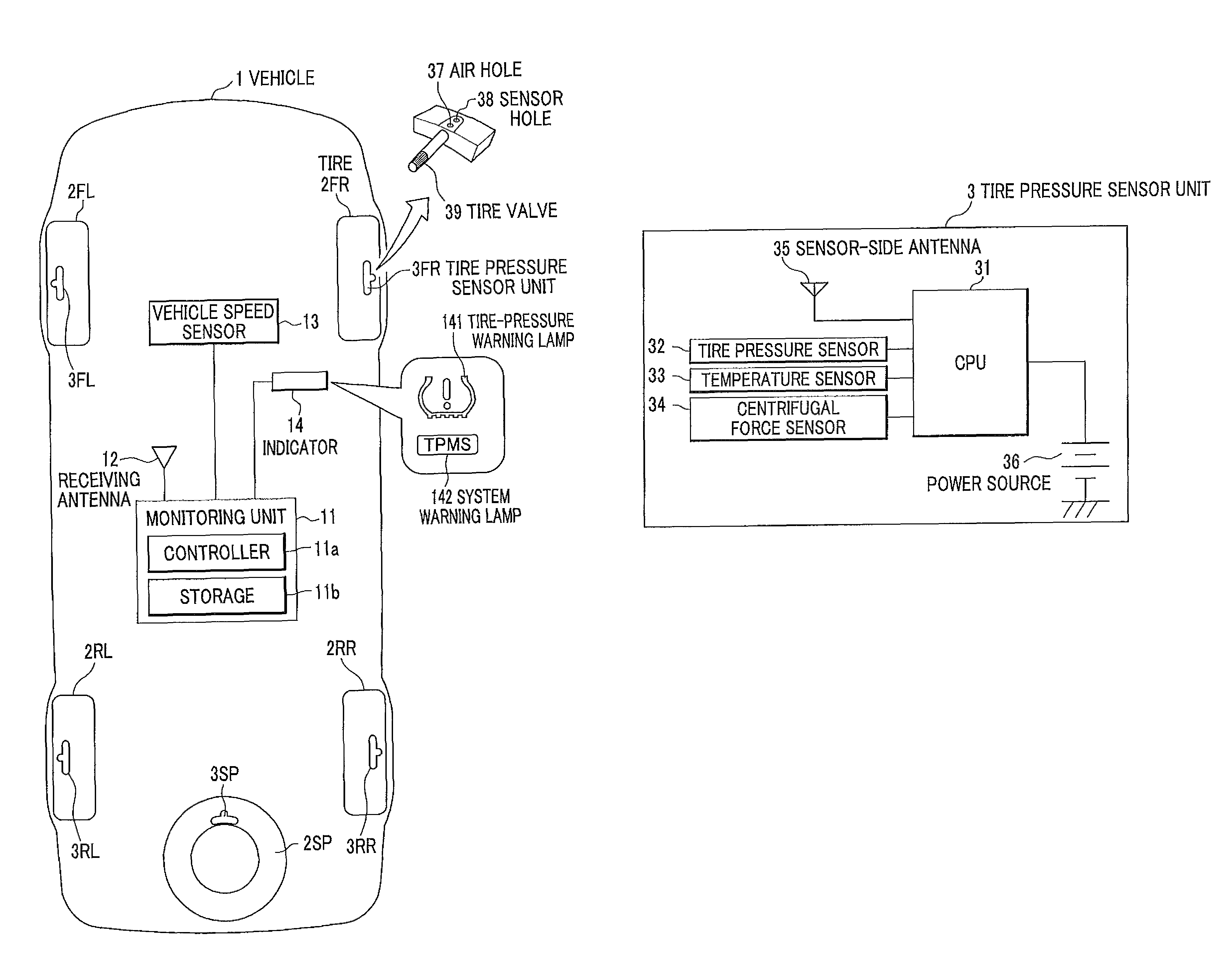
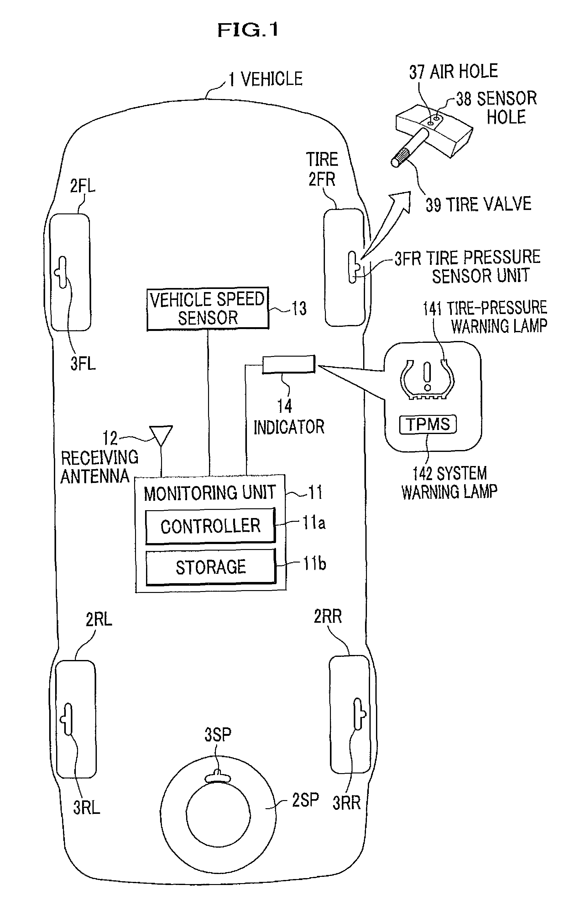
[0041]FIG. 1 is a diagram showing a system configuration of a vehicle equipped with a tire pressure monitoring system according to the embodiment of the present invention.

[0042]As shown in FIG. 1, a vehicle 1 has a front part of the vehicle 1 that is drawn at the upper part of the diagram, the vehicle 1 is of a four-wheel vehicle having four rotating wheels (i.e., running wheels) of a front-right tire 2FR, a front-left tire 2FL, a rear-right tire 2RR, and a rear-left tire 2RL, and further has a spare tire 2SP loaded in the rear part of the vehicle 1. The tires 2FR, 2FL, 2RR, 2RL and 2SP have a tire pressure monitored by respective tire pressure sensor units 3FR, 3FL, 3RR, 3RL and 3SP.

[0043]Note that a word “wheel” stands for a combination of a wheel and a tire attached thereto, but in the present embodiment, a word “wheel” and a word “tire” are equivalently used. ...


PUM


Abstract

A tire pressure monitoring system distinguishes a mounted tire from a non-mounted tire, and which automatically changes over IDs and tire-pressure thresholds without any exclusive apparatuses. A tire pressure monitoring unit stores an identification code of a tire pressure sensor unit and a tire-pressure set value as a pair. While a vehicle is traveling at a speed equal to or faster than a predetermined vehicle speed, if an identification code received within a predetermined time coincides with any one of identification codes of registered tires and the number of coinciding identification codes is equal to the number of tires, and, at least one of the coinciding identification codes is an identification code other than specified identification codes, the specified identification codes are replaced with those coinciding identification codes which are newly specified as respective identification codes of tire pressure sensor units mounted in tires mounted on the vehicle.

Description

CROSS REFERENCE TO RELATED APPLICATION[0001]This application claims the foreign priority benefit under Title 35, United States Code, §119(a)-(d) of Japanese Patent Application No. 2009-127908, filed on May 27, 2009 in the Japan Patent Office, the disclosure of which is herein incorporated by reference in its entirety.BACKGROUND OF THE INVENTION[0002]1. Field of the Invention[0003]The present invention relates to a tire pressure monitoring system which directly measures a tire pressure.[0004]2. Description of the Related Art[0005]A TPMS (Tire Pressure Monitoring System) monitors pressures of respective tires while a vehicle is traveling, and notifies reduction of a tire pressure to the driver of the vehicle when the pressure of a tire decreases while the vehicle is traveling. Installation of such a TPMS in a vehicle to be newly sold becomes an obligation in North America.[0006]TPMSs can be roughly divided into an indirect type and a direct type (sensor type).[0007]A typical example o...

Claims


Application Information

Patent Timeline
Patent Type & Authority Patents(United States)
IPC IPC(8): B60C23/00
CPCB60C23/0408B60C23/0415
Inventor ISOMURA, MAKOTOBESSHO, MAKOTO
Owner HONDA MOTOR CO LTD
Learn More