Supercavitating projectile tracking system and method

a projectile tracking and supercavitation technology, applied in direction finders, direction finders using ultrasonic/sonic/infrasonic waves, instruments, etc., can solve the problems of unreliable conventional acoustic ranging techniques, inability to track underwater projectiles at high speed, and inability to achieve high-speed underwater projectile tracking. , to achieve the effect of quick determination of the trajectory of the underwater obj

Inactive Publication Date: 2012-10-30
THE UNITED STATES OF AMERICA AS REPRESENTED BY THE SECRETARY OF THE NAVY
View PDF13 Cites 0 Cited by
  • Summary
  • Abstract
  • Description
  • Claims
  • Application Information

AI Technical Summary

Benefits of technology

[0023]Accordingly, the present invention provides a system for tracking an underwater object traveling at near sonic or supersonic speeds, which may comprise elements such as, for example, a plurality of randomly distributed passive pressure transducers at positions offset from a path of the underwater object. The pressure transducers detect a peak transient pressure produced in response to a changing pressure field created by the underwater object. A data flow path is utilized for transferring data produced by the plurality of randomly distributed passive pressure transducers. At least one processor is programmed to utilize the data produced by the plurality of randomly distributed passive pressure transducers to quickly determine a trajectory of the underwater object.

Problems solved by technology

The tracking of a high speed (above the incompressible limit, about 0.3 Mach) underwater projectiles with conventional acoustic range systems, several of which are discussed hereinafter, is impractical.
As the sonic speed is approached or reached, conventional acoustic ranging techniques are unreliable.
Moreover, the high-speed projectile in relation to the acoustic propagation from the test body creates great difficulty in accurately determining the position from which the acoustic radiation originated.
This patent is limited in many ways.
Real time solutions are not available.
Moreover, Kuklinski does not necessarily provide solutions for a number of desirable variables within a desired error tolerance including ballistic drag and initial velocity (or velocity adjacent the first sensor).
The above cited prior art does not disclose a method to determine the position in space, the position in time, and the track of a traveling underwater body from a set of data which may arise from randomly spaced passive acoustic sensors.

Method used


Image

  • Supercavitating projectile tracking system and method
  • Supercavitating projectile tracking system and method
  • Supercavitating projectile tracking system and method

Examples


Embodiment Construction

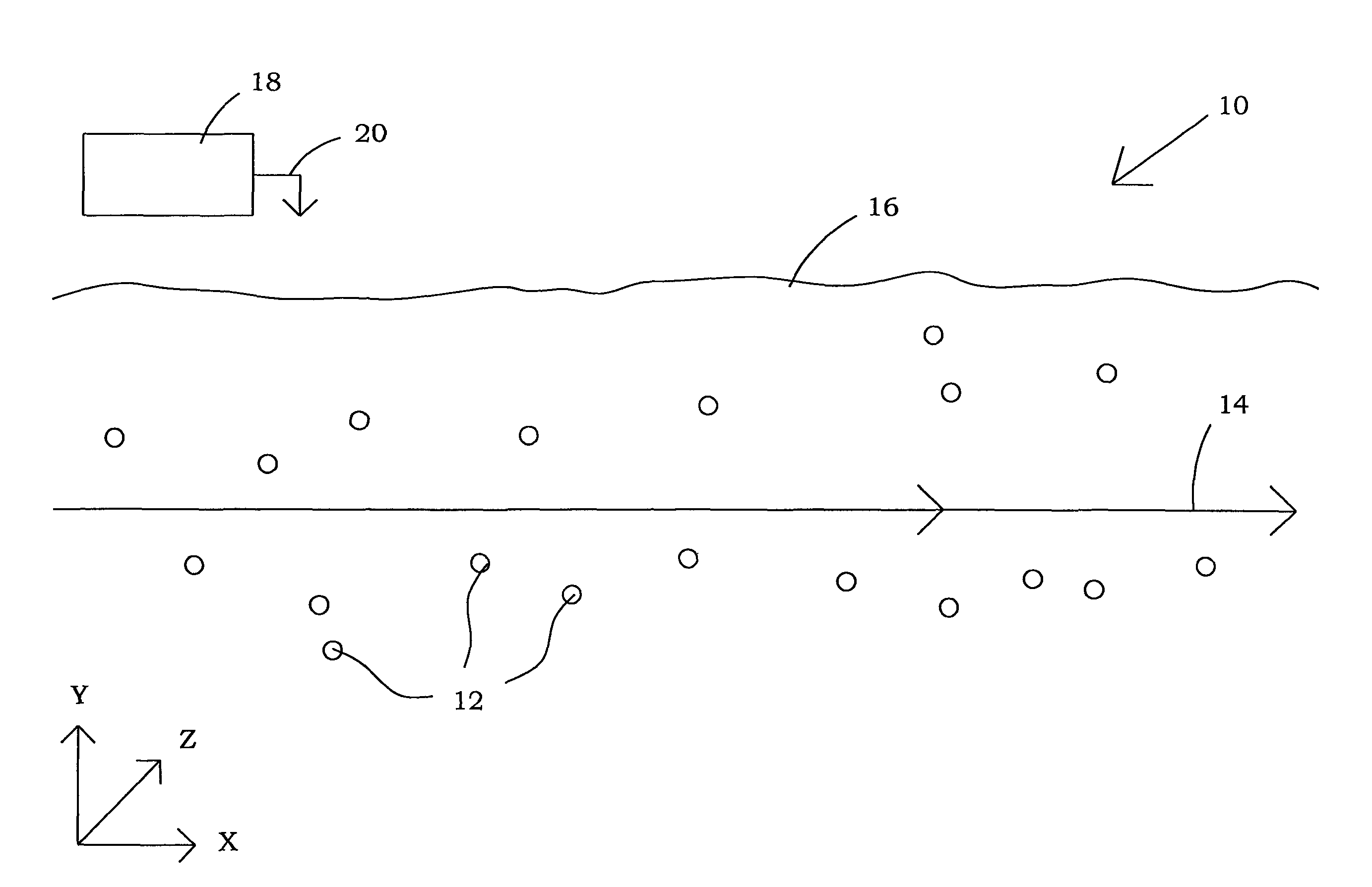
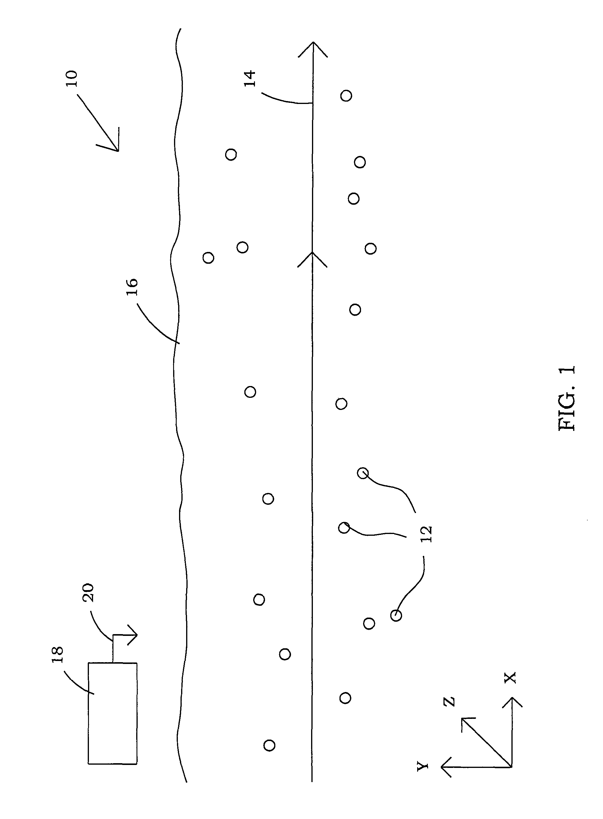
[0036]Referring now to the drawings, and more particularly, to FIG. 1 there is shown tracking system 10 which may be utilized to measure variables which describe the three-dimensional underwater track or path 14 of a supercavitating vehicle under surface 16 of a body of water. In this embodiment, passive acoustic or pressure transducers 12 are utilized to measure a pressure field produced by a moving supercavitating vehicle. The present invention provides a low-cost, reusable, and robust system to measure the performance of projectiles in an open range environment.

[0037]In one embodiment of the invention, passive acoustic or pressure transducers 12 may be randomly distributed along path 14 of the supercavitating vehicle. The information from the transducers is provided to computer 18 utilizing data flow path 20, which may comprise any suitable means for transferring signals from passive acoustic or pressure transducers 12 to computer 18 including wireless, wired or fiber optic trans...


PUM


Abstract

A system for three-dimensional tracking of high speed undersea projectiles may utilize a distributed field of randomly positioned passive acoustic sensors. The system measures variables related to the pressure field generated by a supercavitating projectile in flight wherein the amplitude of the pressure generated at a point in space is related to the projectile dimensions, velocity, and trajectory. The system iteratively processes data from the sensors to measure launch velocity, flight direction (trajectory), ballistic coefficient (drag), and / or maximum range.

Description

STATEMENT OF GOVERNMENT INTEREST[0001]The invention described herein may be manufactured and used by or for the Government of the United States of America for governmental purposes without the payment of any royalties thereon or therefore.CROSS-REFERENCE TO RELATED PATENT APPLICATIONS[0002]None.BACKGROUND OF THE INVENTION[0003](1) Field of the Invention[0004]The present invention relates generally to tracking systems and, more particularly, to tracking systems and methods for tracking in real time the trajectory and velocity of underwater objects which may be traveling at high speeds utilizing data which may come from randomly spaced passive pressure sensors.[0005](2) Description of the Prior Art[0006]The tracking of a high speed (above the incompressible limit, about 0.3 Mach) underwater projectiles with conventional acoustic range systems, several of which are discussed hereinafter, is impractical. For bodies that move at very low Mach numbers, acoustic ranging solutions are conve...

Claims


Application Information

Patent Timeline
Patent Type & Authority Patents(United States)
IPC IPC(8): G01S3/80
CPCG01S5/18
Inventor VARGHESE, ABRAHAM N.KUKLINSKI, ROBERTGIESEKE, THOMAS J.
Owner THE UNITED STATES OF AMERICA AS REPRESENTED BY THE SECRETARY OF THE NAVY
Why Eureka
Try Eureka