
Mouth removal method for red-eye detection and correction

a redeye detection and correction technology, applied in the field of mouth removal method for redeye detection and correction, can solve the problems of many challenging problems, false positives still remain, and many problems, and achieve the effect of preserving high computational speed and eye detection ra

Active Publication Date: 2012-10-30
ADVANCED INTERCONNECT SYST LTD
View PDF16 Cites 2 Cited by
  • Summary
  • Abstract
  • Description
  • Claims
  • Application Information

AI Technical Summary

Benefits of technology

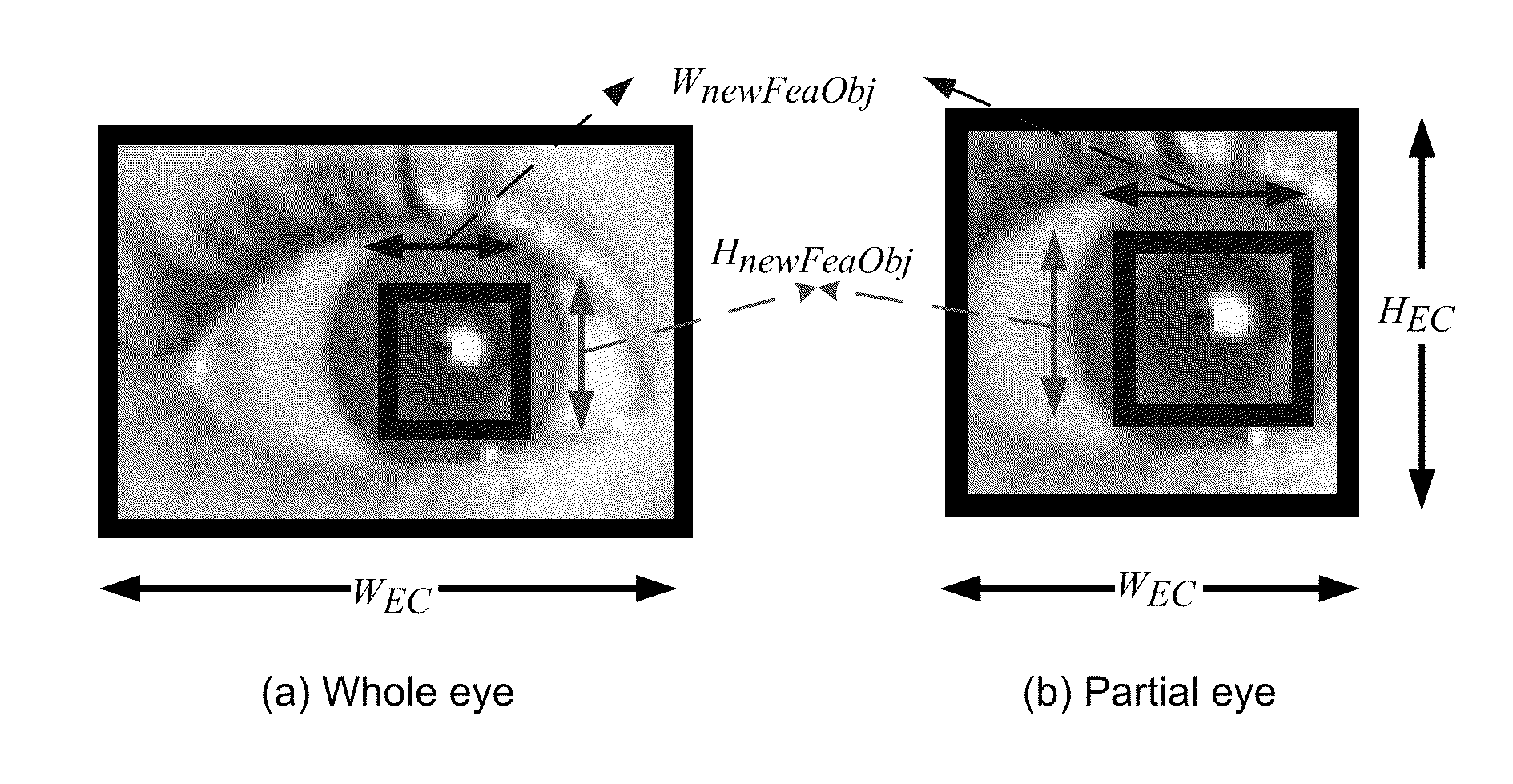
[0004]An object of the present invention is to remove mouth detections (false positives) as red-eye candidates while preserving high-computational speed and eye detection rate.

Problems solved by technology

Though there has been a great deal of progress in red-eye detection and correction in the last few years, many problems remain unsolved.
Research in these areas must confront many challenging problems, especially when dealing with varying illumination, low image quality and resolution, eye size and variations in face orientation, and background changes in complex scenes.
Although these techniques can significantly suppress false detections, some false positives still remain, in particular mouth patterns.
Correction of the mouth area as a falsely detected red-eye object will ruin the picture and disappoint the end user.

Method used


Image

  • Mouth removal method for red-eye detection and correction
  • Mouth removal method for red-eye detection and correction
  • Mouth removal method for red-eye detection and correction

Examples


Embodiment Construction

[0020]In the following detailed description, reference is made to the accompanying drawings that show, by way of illustration, example embodiments of the invention. In the drawings, like numerals describe substantially similar components throughout the several views. These embodiments are described in sufficient detail to enable those skilled in the art to practice the invention. Other embodiments may be utilized and structural, logical and electrical changes may be made without departing from the scope of the present invention. Moreover, it is to be understood that the various embodiments of the invention, although different, are not necessarily mutually exclusive. For example, a particular feature, structure, or characteristic described in one embodiment may be included within other embodiments. The following detailed description is, therefore, not to be taken in a limiting sense, and the scope of the present invention is defined only by the appended claims, along with the full sc...


PUM


Abstract

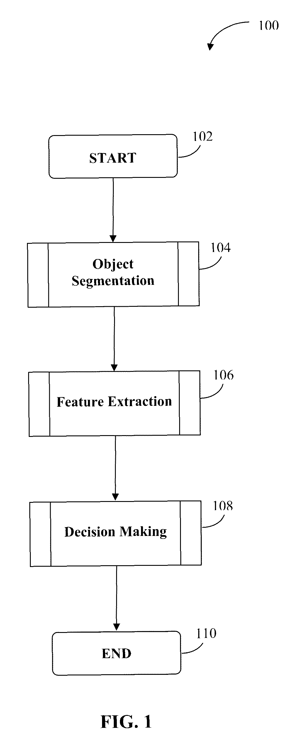
An input image (e.g. a digital RGB color image) is subjected to an eye classifier that is targeted at discriminating a complete eye pattern from any non-eye patterns. The red-eye candidate list with associated bounding boxes that are generated by the red-eye classifier are received. The bounding rectangles are subjected to object segmentation. A connected component labeling procedure is then applied to obtain one or more red regions. The largest red region is then chosen for feature extraction. A number of features are then extracted from this region. Then these features are used to determine if the particular candidate red-eye object is a mouth.

Description

BACKGROUNDField of Invention[0001]Red-eye detection and correction technologies are used in printers, digital cameras, and image editing software to localize and correct the red-eye effects in digital photographs captured using a flash. Though there has been a great deal of progress in red-eye detection and correction in the last few years, many problems remain unsolved. Research in these areas must confront many challenging problems, especially when dealing with varying illumination, low image quality and resolution, eye size and variations in face orientation, and background changes in complex scenes.[0002]In general, early stages of a red-eye detection involve distinguishing between true red-eye objects and a number of incorrectly detected non-red-eye objects (referred to as false positives or falses), which are particularly evident in complex scenes. This false detection processing can be reduced based on the evaluation of the object's color, structural and geometric characteris...

Claims


Application Information

Patent Timeline
Patent Type & Authority Patents(United States)
IPC IPC(8): G06K9/34G06K9/40G06K9/00G06V10/56
CPCG06K9/00234G06K9/4652G06V40/162G06V10/56
Inventor YANG, SUSANWANG, JIE
Owner ADVANCED INTERCONNECT SYST LTD
Learn More