Silencer

a technology of silicon dioxide and silicon plate, applied in the field of silicon plate, can solve the problems of requiring comparatively large space and little space, and achieve the effect of reducing the volume of construction

Active Publication Date: 2012-11-06
PUREM GMBH
View PDF20 Cites 8 Cited by
  • Summary
  • Abstract
  • Description
  • Claims
  • Application Information

AI Technical Summary

Benefits of technology

[0006]The invention is based on the general idea of developing the outlet pipe not as a single pipe but as a pipe arrangement, namely as pipe-in-pipe arrangement. Such a pipe-in-pipe arrangement comprises at least one deflection pipe closed on one end and arranged in the housing of the silencer and an outlet pipe led out of the housing. Through the pipe-in-pipe arrangement, a comparatively long flow path can be realized with short length, which is carried out with the help of suitable deflections. The pipe-in-pipe arrangement can be constructed substantially shorter than a comparable pipe with identical flow length. Investigations have shown that the pipe-in-pipe arrangement achieves damping equivalent to that of a continuous pipe with respect to the low frequencies. At higher frequencies, an even better damping effect is achieved which is attributed to the cross-sectional jumps in the region of the flow deflections.
[0007]The proposed design thus allows a space-reduced realization of a silencer with long flow path in the “outlet pipe” or in the outlet pipe arrangement, with which the desired damping effect for low interference frequencies is additionally guaranteed.
[0008]According to an advantageous embodiment the pipe-in-pipe arrangement can create a flow path which from the outlet chamber to the outlet pipe comprises at least two 180° deflections. Because of this, a three-way layering for the exhaust flow is obtained, which ultimately results in a significant shortening of the outlet pipe arrangement compared with a single pipe.
[0009]With another embodiment it can be provided that the deflection pipe on its closed side comprises a bottom that is concavely curved towards the outlet pipe. Because of this, the through-flow resistance of the silencer can be reduced. In addition or alternatively, the housing or an outer pipe enveloping the deflection pipe can have a bottom that is concavely curved towards the deflection pipe on its side facing the open side of the deflection pipe. Because of this, the 180° deflection is favored, which reduces the through-flow resistance of the silencer.
[0011]According to another advantageous embodiment it can be provided to equip the outlet pipe on its inlet side, that is within the deflection pipe, with a perforation. Such a perforation can reduce the development of higher-frequency noises. In addition or alternatively the outlet pipe can be fastened to the deflection pipe on its inlet side. This produces a stabilization of the outlet pipe within the pipe-in-pipe arrangement. Fastening of the outlet pipe to the deflection pipe can more preferably be carried out also in the region of the perforation.

Problems solved by technology

Comparatively much space is required for this.
Particularly in the case of smaller vehicles only little space is available.

Method used


Image

  • Silencer
  • Silencer
  • Silencer

Examples


Embodiment Construction

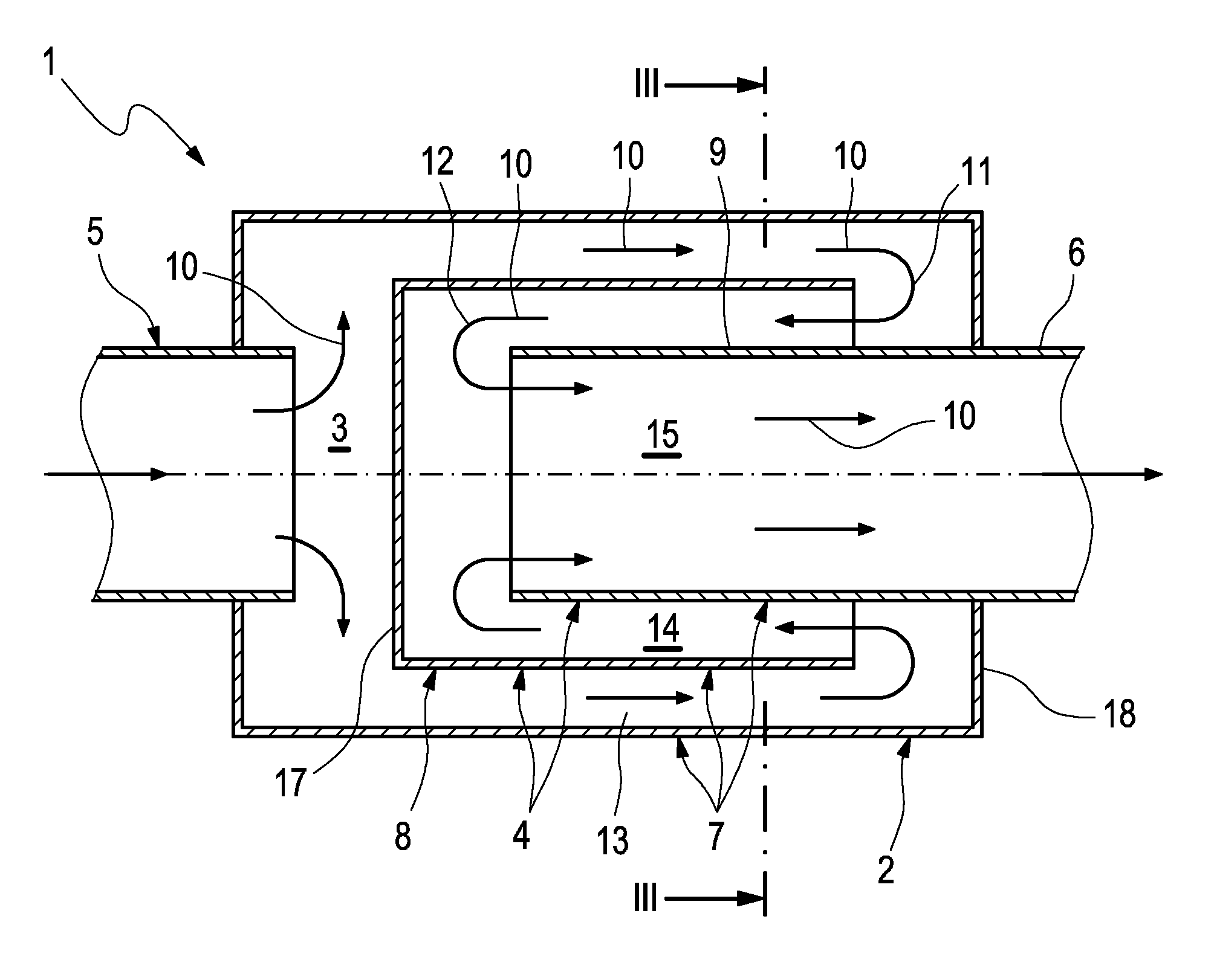
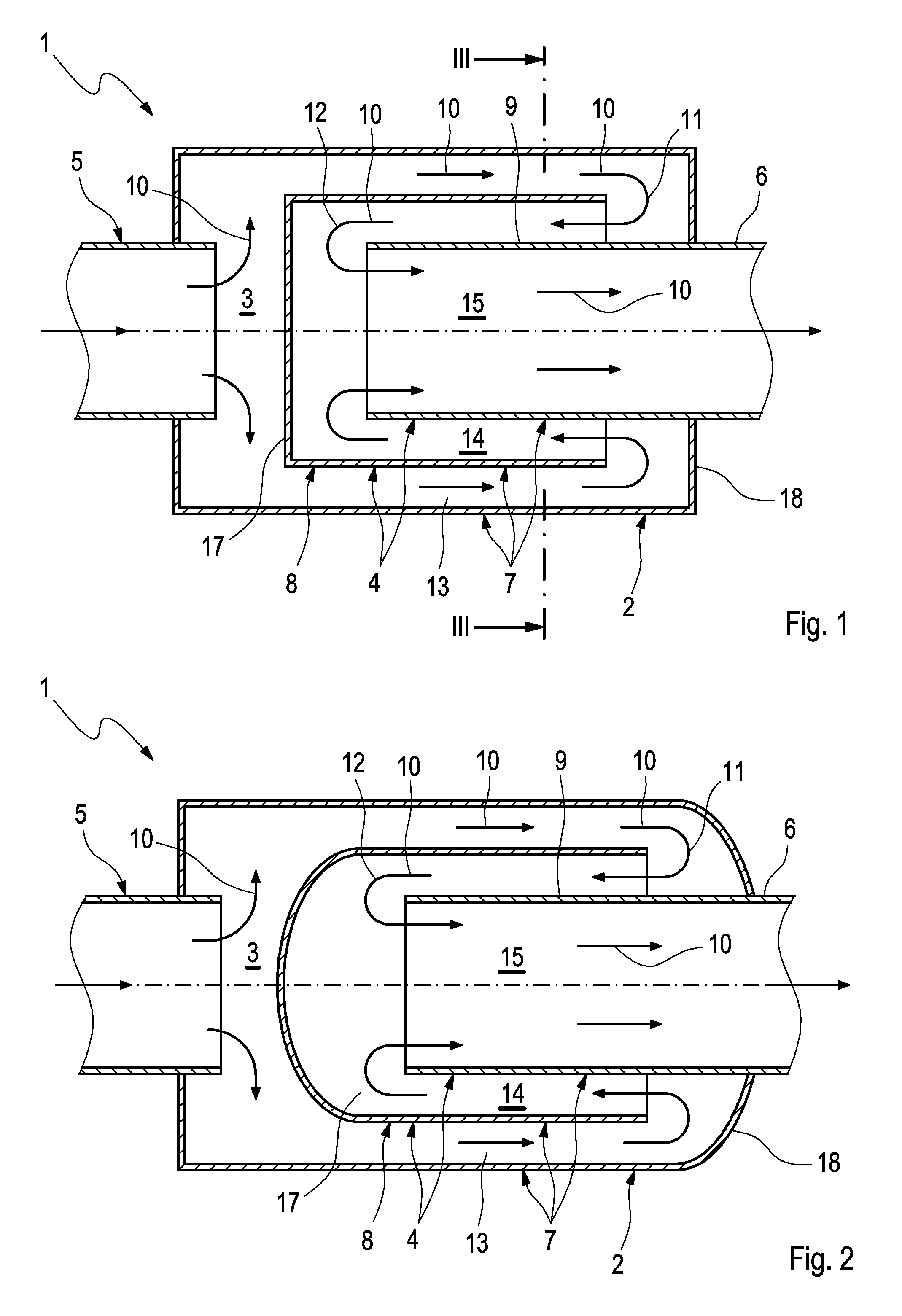
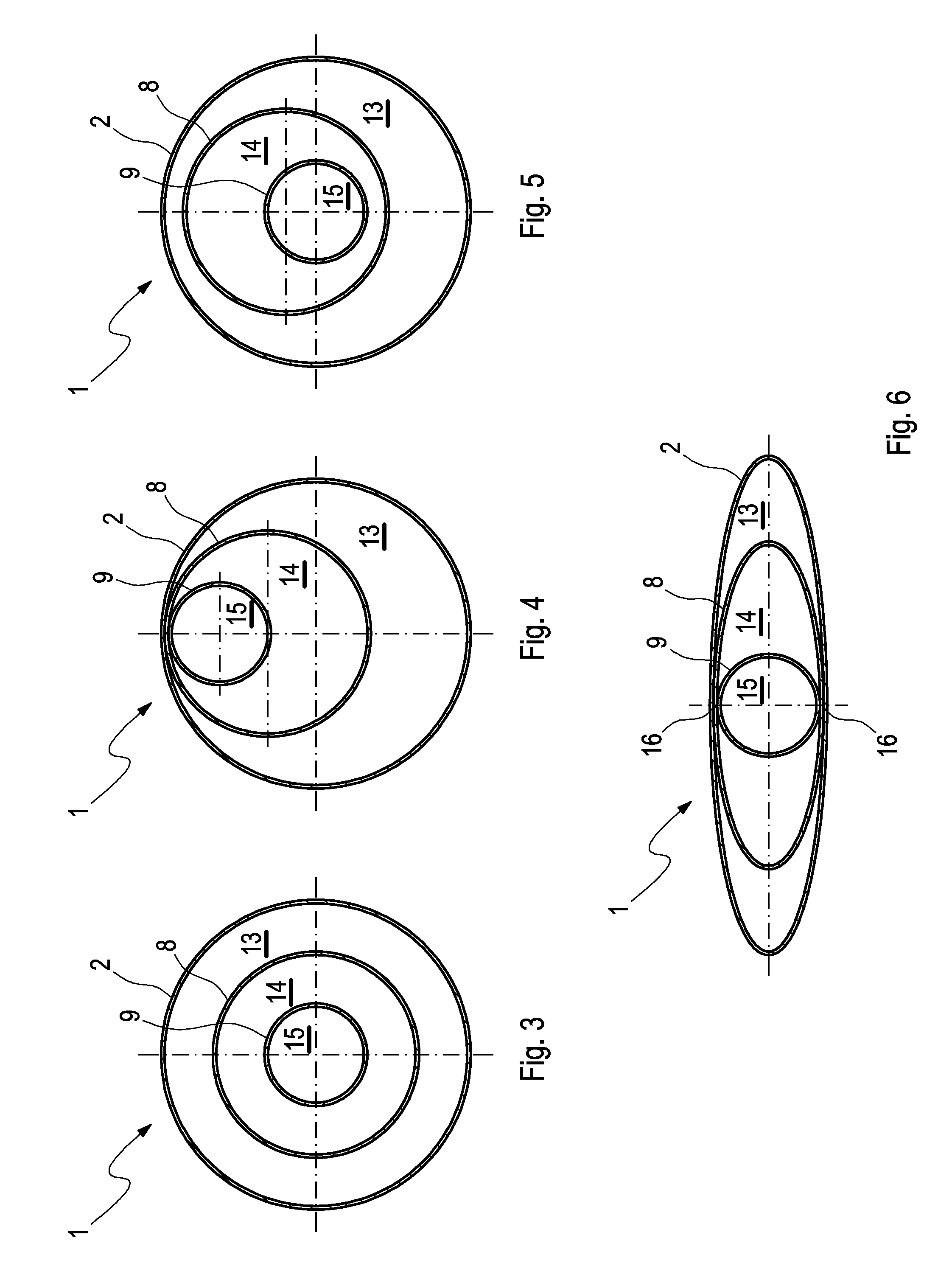
[0023]Referring to the drawings in particular, according to FIGS. 1 and 2 a silencer 1, which preferably is a rear silencer, comprises a housing 2 having an outlet chamber 3. An outlet pipe arrangement 4 is led out of the housing 2, namely in such a manner that the outlet pipe arrangement 4 on the inlet side is fluidically connected to the outlet chamber 3 located in the housing 2.

[0024]The silencer 1 in the installed state is incorporated in an exhaust system 5 which is only partially evident here and which belongs to a combustion engine that is not shown here, which can preferentially be arranged in a motor vehicle. Provided that the silencer 1 is preferably developed as rear silencer 1, it is located in an end region of the exhaust system 5 on the outlet end. In particular, the outlet pipe arrangement 4 led out of the housing 2 comprises a so-called tailpipe 6 of the exhaust system 5 or is connected to said tailpipe 6. The tailpipe 6 is characterized in that it comprises the mout...


PUM


Abstract

A silencer, particularly rear silencer, for an exhaust system of a combustion engine, particularly of a motor vehicle, has a housing in which an outlet chamber is located. An outlet pipe arrangement leads out of the housing which on the inlet side is fluidically connected to the outlet chamber. A particularly compact design can be realized if the outlet pipe arrangement is configured as pipe-in-pipe arrangement including at least one deflection pipe closed on one side and arranged in the housing and an outlet pipe led out of the housing.

Description

CROSS REFERENCE TO RELATED APPLICATIONS[0001]This application claims the benefit of priority under 35 U.S.C. §119 of German Patent Application DE 10 2010 008 403.4 filed Feb. 18, 2010, the entire contents of which are incorporated herein by reference.FIELD OF THE INVENTION[0002]The present invention relates to a silencer (also known as a muffler), particularly a rear silencer, for an exhaust system of a combustion engine, particularly of a motor vehicle.BACKGROUND OF THE INVENTION[0003]In an exhaust system a so-called rear silencer is usually located at an end section of the exhaust system on the outlet side. An outlet pipe leading out of the rear silencer usually forms a so-called tailpipe or is connected to such a tailpipe. The tailpipe has the mouth opening of the exhaust system that is open to the environment. Usually a silencer comprises a housing in which an outlet chamber is located and the outlet pipe is led out from said outlet chamber. For damping low-frequency noises it i...

Claims


Application Information

Patent Timeline
Patent Type & Authority Patents(United States)
IPC IPC(8): F01N1/08
CPCF01N1/084
Inventor GORKE, PETERPOMMERER, MICHAEL
Owner PUREM GMBH
Why Eureka
Try Eureka