Shroud assembly with discourager

Active Publication Date: 2012-11-06
GENERAL ELECTRIC CO
View PDF11 Cites 24 Cited by
  • Summary
  • Abstract
  • Description
  • Claims
  • Application Information

AI Technical Summary

Problems solved by technology

However, industrial gas turbine and aircraft engine shrouds operate in a high temperature environment and therefore require cooling to obtain a useful design life cycle.

Method used


Image

  • Shroud assembly with discourager
  • Shroud assembly with discourager
  • Shroud assembly with discourager

Examples


Embodiment Construction

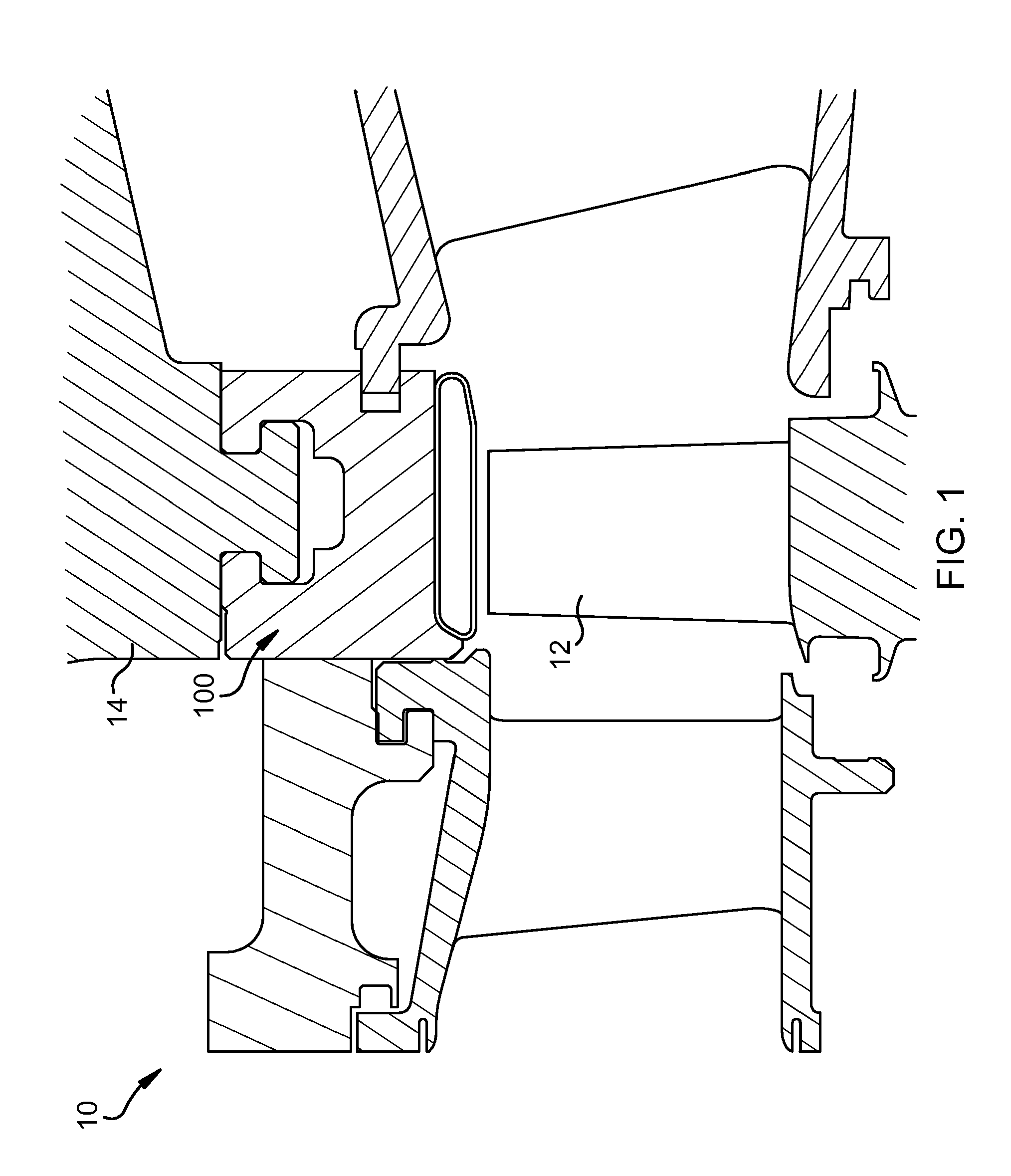
[0014]Turning to the figures, FIG. 1 shows a turbine shroud assembly 100 within a turbine 10 (partially shown in FIG. 1) according to an embodiment of this invention. Turbine 10 includes at least one rotating blade 12 and an outer casing 14. According to embodiments of this invention, at least one shroud assembly 100 is positioned between rotating blade 12 and outer casing 14. As also known in the art, an operative fluid (e.g., combustion gas or steam) flows through the turbine, impinging on rotating blades 12. It should be noted that, as will be appreciated by one of ordinary skill in the art, turbine 10 can be any type of turbine, such as a steam turbine, gas turbine, combined gas and steam turbine, LP turbine, IP turbine, single flow steam turbine, combined-cycle turbine, opposed-flow turbine, and / or HP turbines.

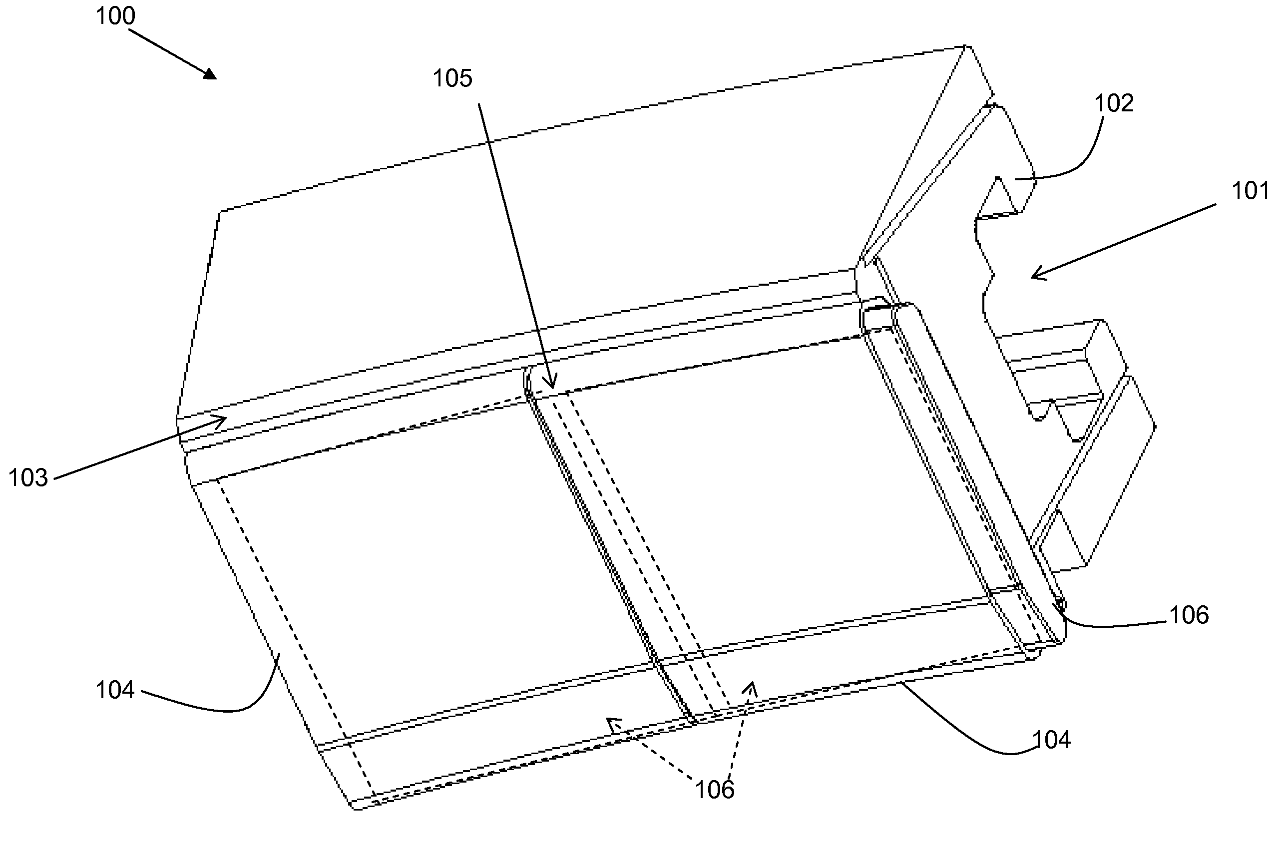
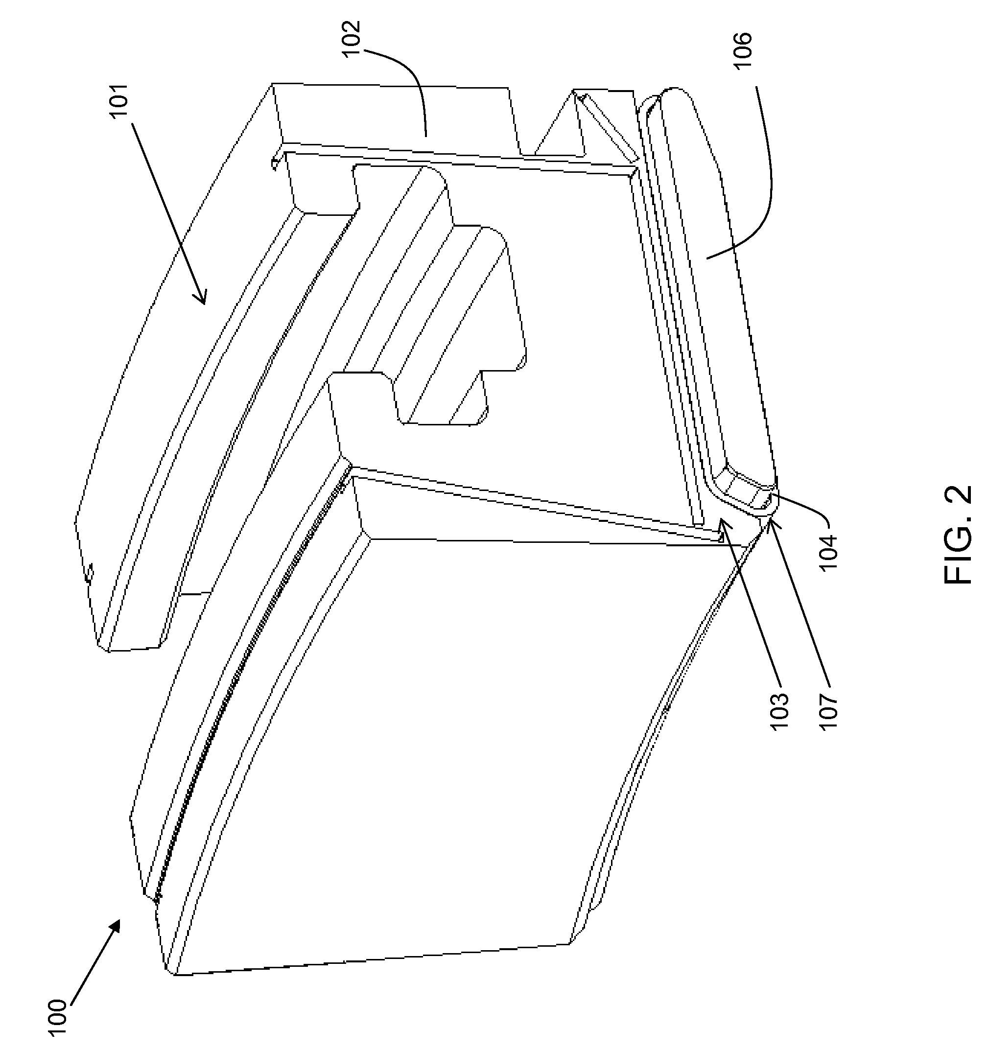
[0015]A shroud assembly 100 according to embodiments of this invention is shown in FIG. 2. Turbine shroud assembly 100 includes an outer shroud 102, having a first side 1...


PUM


Abstract

A turbine shroud assembly is disclosed, the shroud assembly including an outer shroud, at least one inner shroud attached to the outer shroud, and at least one discourager enclosed within the inner shroud. The discourager prevents the hot gas or steam in the turbine from having a direct line of access to the outer shroud. In one embodiment, one inner shroud is provided for the shroud assembly, with one discourager enclosed within the inner shroud, the discourager positioned offset from the inner shroud so as to extend past the inner shroud and into an inner shroud of a neighboring shroud assembly. In another embodiment, a plurality of inner shrouds are provided, each inner shroud enclosing a discourager, the discouragers being adjacent to each other within the inner shrouds and positioned offset from the inner shrouds so as to cover a gap between the inner shrouds.

Description

BACKGROUND OF THE INVENTION[0001]The present invention relates generally to turbine shroud assemblies and more particularly to a discourager for use in a turbine shroud assembly.[0002]Shrouds are used in turbines and engines to act as an interface between rotating blades and a casing structure. The shroud provides tight tip clearance to the blades, and provides a mounting for the nozzles. Typically, such shrouds are made of a metal material. However, industrial gas turbine and aircraft engine shrouds operate in a high temperature environment and therefore require cooling to obtain a useful design life cycle. An alternative to using a metal shroud with cooling air is to use a ceramic matrix composite (CMC) material for the shroud, thus eliminating the required cooling of the shroud due to the CMC's superior temperature capability over metal. The CMC shroud typically includes seals to prevent the high heat at the end of the shroud nearest the gas / steam path from reaching the end neare...

Claims


Application Information

Patent Timeline
Patent Type & Authority Patents(United States)
IPC IPC(8): F01D11/08
CPCF01D9/04F01D11/00F01D25/265F05D2240/11Y02T50/672Y02T50/60
Inventor FOSTER, GREGORY THOMASCRESPO, ANDRES JOSE GARCIAROBERTS, HERBERT CHIDSEY
Owner GENERAL ELECTRIC CO
Why Eureka
Try Eureka