
Centralized load management for use in controllably recharging vehicles equipped with electrically powered propulsion systems

a technology of electrically powered propulsion system and load management system, which is applied in non-electric variable control, process and machine control, instruments, etc., can solve the problems of fractions of telecommunication costs for operating the load management system, and achieve the effect of enhancing the operation of the centralized vehicle load management system, facilitating rapid recharging of vehicles, and controlling the charging of a large number of vehicles

Inactive Publication Date: 2012-11-06
LAVA FOUR
View PDF11 Cites 18 Cited by
  • Summary
  • Abstract
  • Description
  • Claims
  • Application Information

AI Technical Summary

Benefits of technology

"The present invention is a system for managing the delivery of power to electric vehicles to prevent overloads on the power grid. The system uses a hierarchical approach to detect and remedy overloads at different levels of the grid. It integrates with the vehicle's metering capabilities and location information to feed the necessary data into the utility's load management system. The system can manage the charging of the vehicle's battery banks and act as a power source to other vehicles. It can also use intelligent self-identifying power sources and self-metering vehicles for efficient load management. The technical effects of the invention include reducing costs, simplifying deployment, and enabling ubiquitous access by any vehicle at any charging plug."

Problems solved by technology

The cost to implement such a system is just a few dollars per vehicle, and the cost to operate the load management system is fractions of pennies in telecommunication cost per vehicle being load managed.

Method used


Image

  • Centralized load management for use in controllably recharging vehicles equipped with electrically powered propulsion systems
  • Centralized load management for use in controllably recharging vehicles equipped with electrically powered propulsion systems
  • Centralized load management for use in controllably recharging vehicles equipped with electrically powered propulsion systems

Examples


utility embodiment

Multi-Utility Embodiment

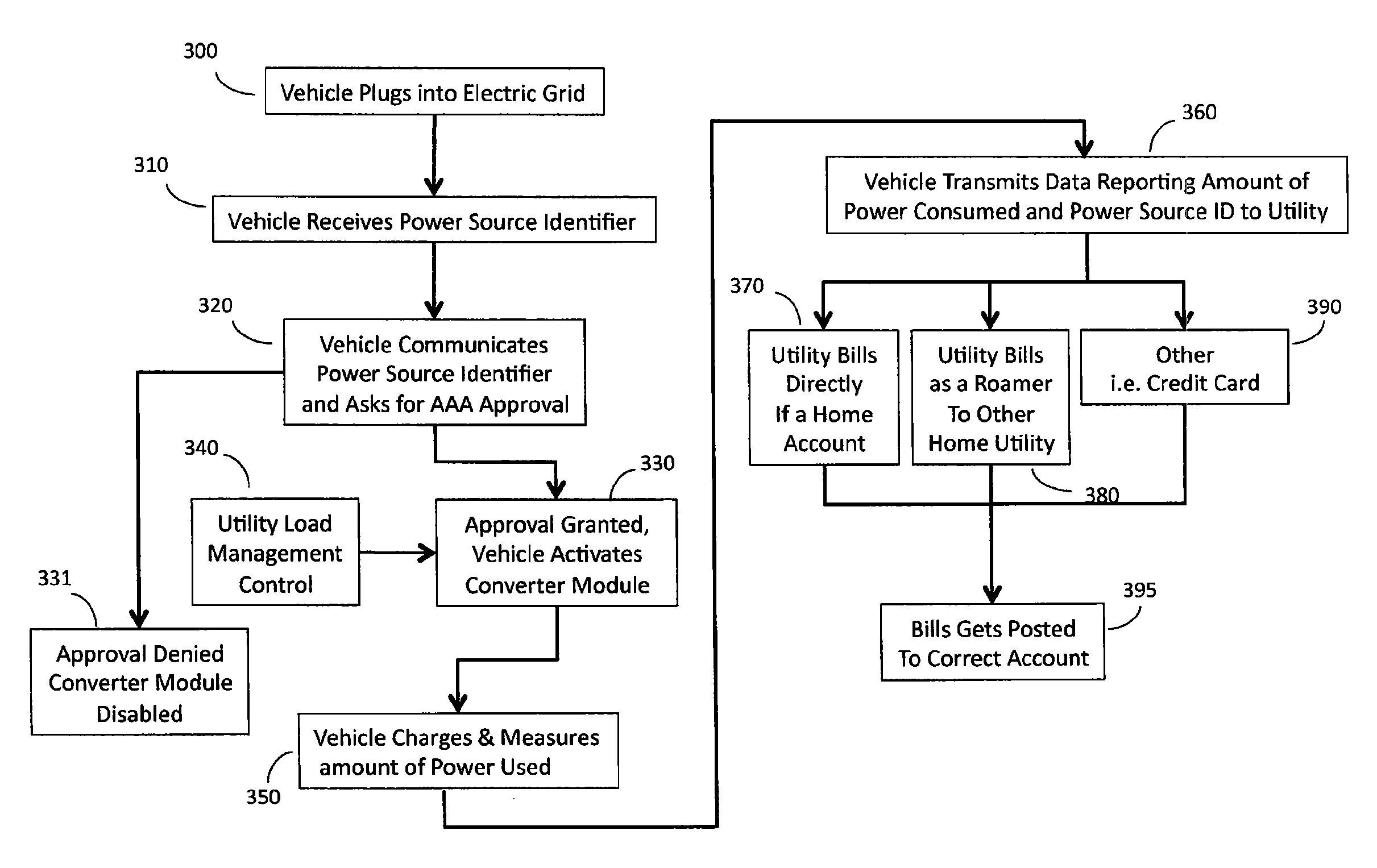
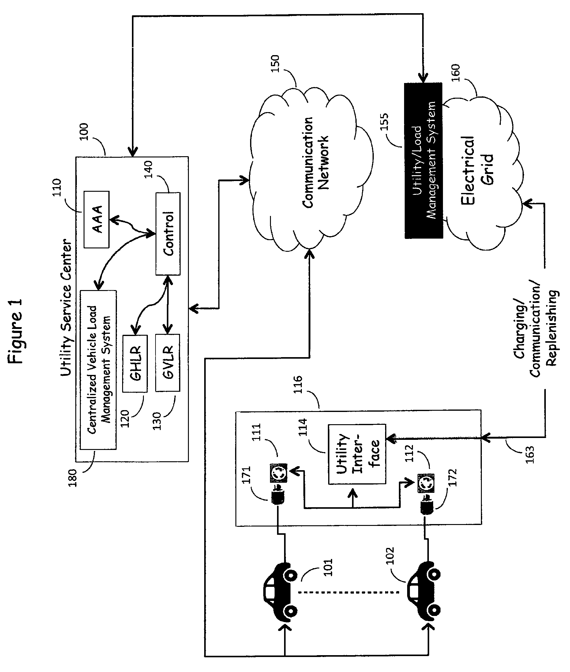
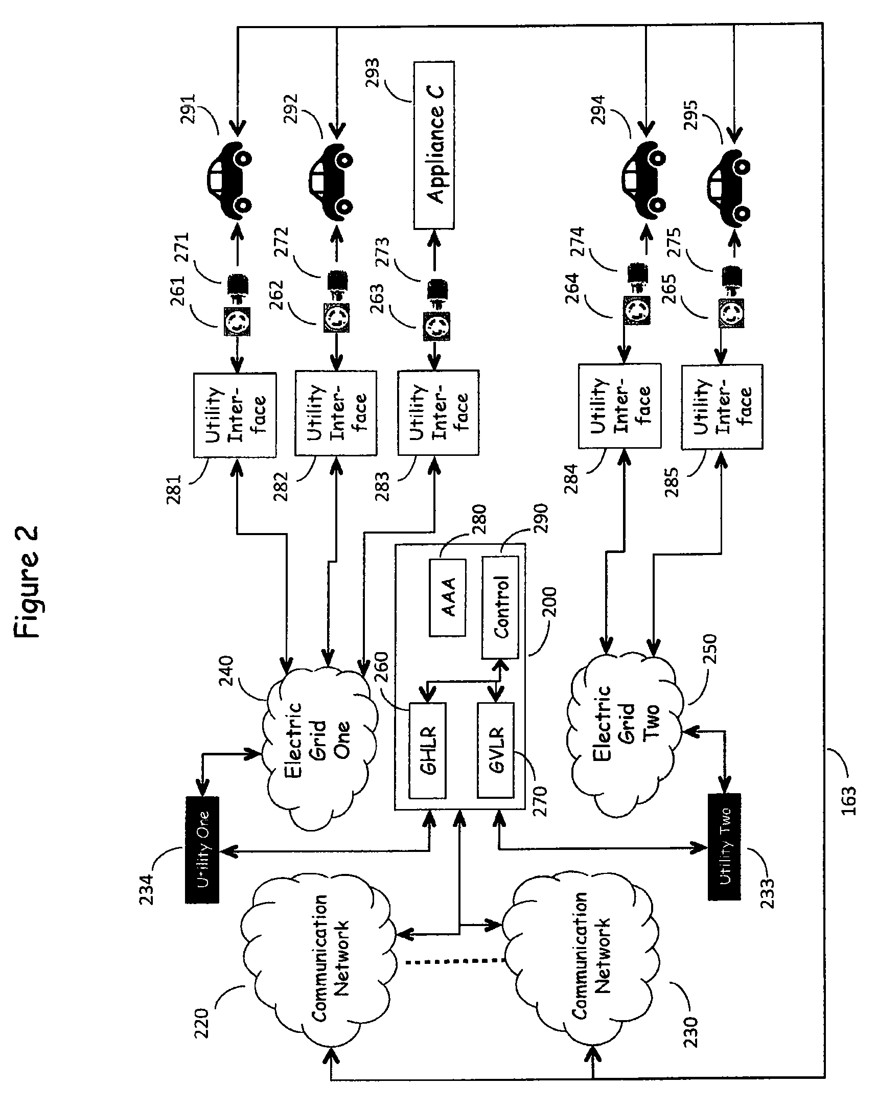
[0044]FIG. 1 is in reality a multidimensional network in which N electric utilities are served by M Electric Power Grids with corresponding communication networks, as shown in FIG. 2. Electric Power Grids 240, 250 shown in FIG. 2 represent the source of electric power as provided by multiple utility companies which serve a wide geographic area and provide electric power to a multitude of customers via utility interfaces 281-285. The utility interfaces 281-285 serve to measure the energy consumption by the various outlet connected loads, such as Vehicles 291-295. These elements represent the existing, present day electric power delivery infrastructure as described above. Electric power traditionally flows from the Electric Power Grid 240, 250 to the utility interfaces 281-285 via the Electric Power Grid and thence to the customer's loads—Vehicles 291-295 via plug 271-275-outlet 261-265 combinations, but power also can flow in the reverse direction, from the ve...


PUM


Abstract

The Centralized Vehicle Load Management System is hierarchical in nature in that it detects and remediates an overload which can be highly localized at one or more electrical substations or an overload which is widely distributed as a cumulative set of sub-critical loads. The Centralized Vehicle Load Management System operates to determine the load presented to the Electric Power Grid by vehicles which are served by service disconnects which are located at a plurality of points on the Electric Power Grid. The Centralized Vehicle Load Management System regulates the demands presented by the vehicles to the E-Grid thereby to spread the load presented to the Electric Power Grid over time to enable the controllable charging of a large number of vehicles.

Description

CROSS-REFERENCE TO RELATED APPLICATIONS[0001]This Application is a continuation-in-part of U.S. application Ser. No. 12 / 329,349 tided “Self-Identifying Power Source For Use In Recharging Vehicles Equipped With Electrically Powered Propulsion Systems” filed 5 Dec. 2008, and U.S. application Ser. No. 12 / 329,368 titled “System For On-Board Metering Of Recharging Energy Consumption In Vehicles Equipped With Electrically Powered Propulsion Systems” filed 5 Dec. 2008, and U.S. application Ser. No. 12 / 329,389 titled “Network For Authentication, Authorization, and Accounting Of Recharging Processes For Vehicles Equipped With Electrically Powered Propulsion Systems” filed 5 Dec. 2008. In addition, this Application is related to a US Application tided “Sub-Network Load Management For Use In Recharging Vehicles Equipped With Electrically Powered Propulsion Systems”, a US Application titled “Dynamic Load Management For Use In Recharging Vehicles Equipped With Electrically Powered Propulsion Sys...

Claims


Application Information

Patent Timeline
Patent Type & Authority Patents(United States)
IPC IPC(8): H02J7/14H02J7/04H02J7/00
CPCG07F15/005B60L11/1844H02J3/14H02J13/0024H02J13/0086H02J13/0089B60L11/1816B60L11/184B60L11/1842B60L11/1846B60L11/1848G07G3/006Y02T10/7291B60L2240/72Y02T10/7005Y02T90/163Y02T90/169Y02T90/121Y02T90/14Y02T90/128Y04S10/126Y04S30/14Y02E60/721Y02T10/7072B60L53/14B60L53/64B60L55/00B60L53/63B60L53/65B60L53/665H02J13/00009H02J2310/48H02J2310/60H02J13/00028H02J13/00034Y02E60/00Y02T10/70Y02T10/72Y02T90/12Y02T90/167Y02T90/16Y04S20/222Y02B70/3225
Inventor MCKENNA, DANIEL BERNARD
Owner LAVA FOUR
Learn More