
System and method for maintaining position of a wellbore servicing device within a wellbore

a technology of servicing device and wellbore, which is applied in the direction of drilling pipes, drilling holes/well accessories, directional drilling, etc., can solve the problems of inability to provide centralizing and/or selective radial placement of secured wellbore servicing device within the wellbore, and the hold-down system is susceptible to becoming stuck or otherwise incapable of easy selective dislodging from the wellbore and/or the casing, etc., to achieve the effect of increasing the curvature of th

Active Publication Date: 2012-11-13
HALLIBURTON ENERGY SERVICES INC
View PDF43 Cites 14 Cited by
  • Summary
  • Abstract
  • Description
  • Claims
  • Application Information

AI Technical Summary

Benefits of technology

The patent describes a method and device for maintaining the position of a wellbore servicing device in a wellbore. The device uses a pressure activated hold-down tool that is connected to the servicing device. The hold-down tool can change its position in response to changes in fluid pressure, and it is designed to engage with a feature of the wellbore to prevent the device from moving longitudinally. This allows for better stability and efficiency during servicing of the wellbore.

Problems solved by technology

However, some hold-down systems are susceptible to becoming stuck or otherwise incapable of easy selective dislodging from the wellbore and / or the casing as a result of sand, dirt, and / or other matter interfering with operation of the hold-down systems.
Further, some hold-down systems require special and / or extraneous wellbore service procedures to activate and / or deactivate the hold-down systems.
Some hold-down systems are capable of providing sufficient holding forces but fail to provide any centralizing and / or selective radial placement of the secured wellbore servicing device within the wellbore.

Method used


Image

  • System and method for maintaining position of a wellbore servicing device within a wellbore
  • System and method for maintaining position of a wellbore servicing device within a wellbore
  • System and method for maintaining position of a wellbore servicing device within a wellbore

Examples


Embodiment Construction

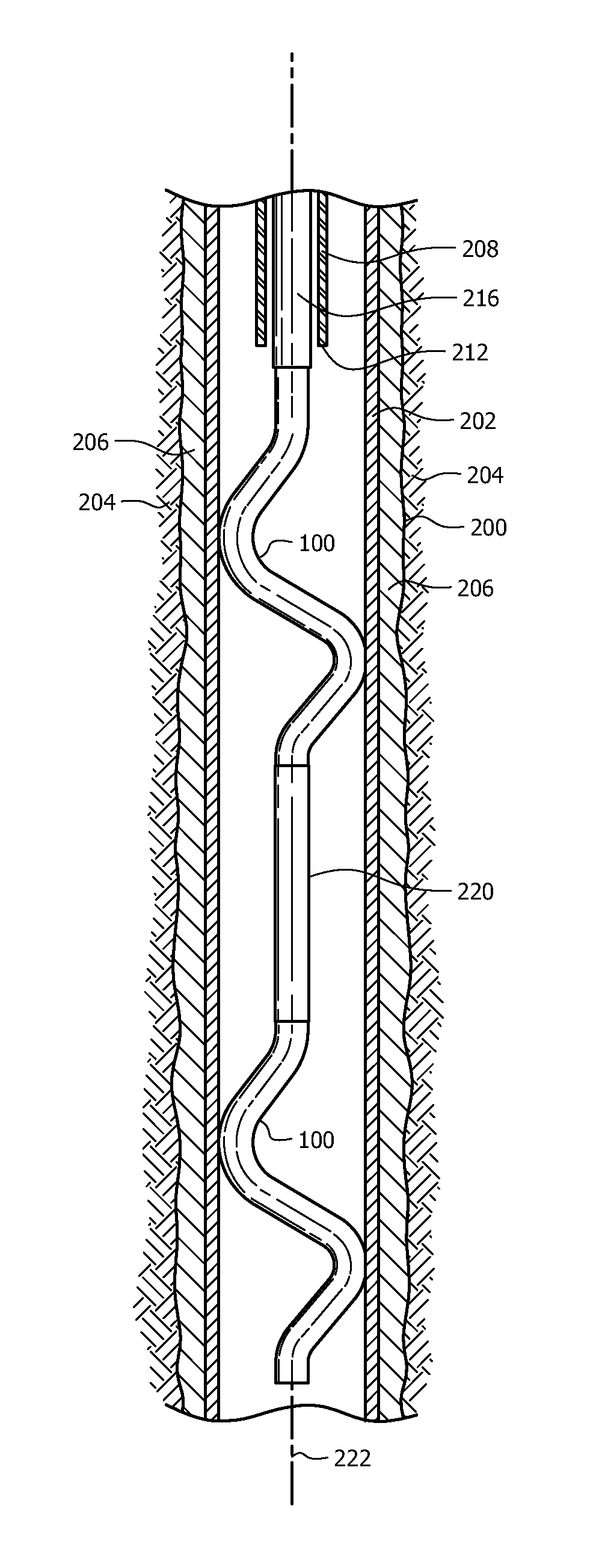
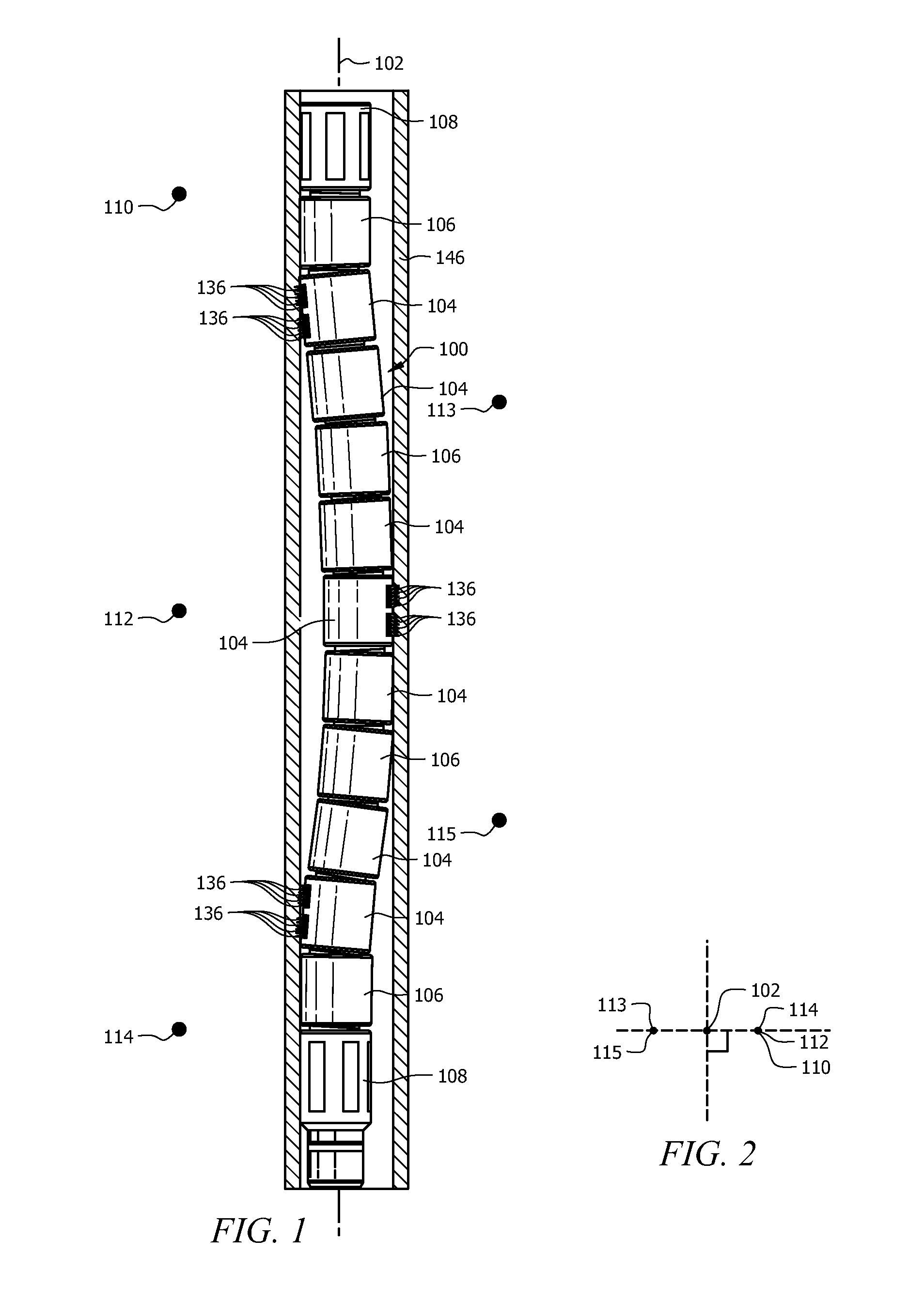
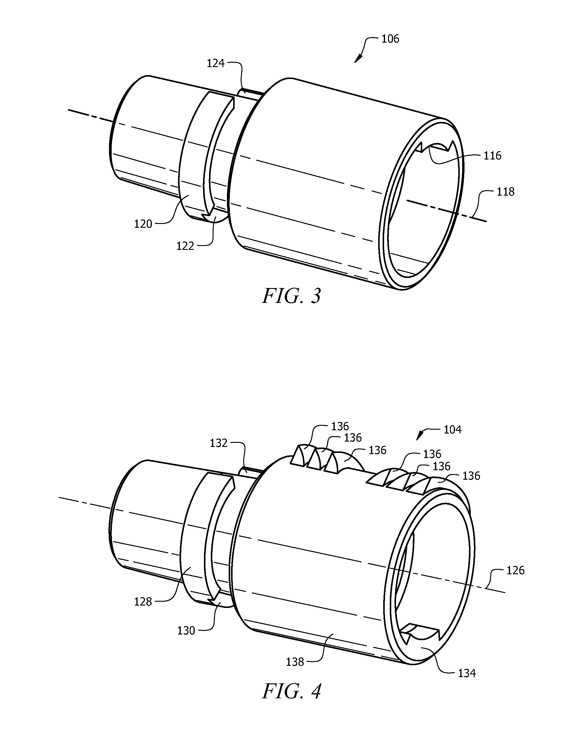
[0023]In the drawings and description that follow, like parts are typically marked throughout the specification and drawings with the same reference numerals, respectively. The drawing figures are not necessarily to scale. Certain features of the invention may be shown exaggerated in scale or in somewhat schematic form and some details of conventional elements may not be shown in the interest of clarity and conciseness.

[0024]Unless otherwise specified, any use of any form of the terms “connect,”“engage,”“couple,”“attach,” or any other term describing an interaction between elements is not meant to limit the interaction to direct interaction between the elements and may also include indirect interaction between the elements described. In the following discussion and in the claims, the terms “including” and “comprising” are used in an open-ended fashion, and thus should be interpreted to mean “including, but not limited to . . . ”. Reference to up or down will be made for purposes of ...


PUM


Abstract

A method of maintaining a location of a wellbore servicing device includes connecting a pressure activated hold-down tool (PAHT) to the wellbore servicing device, delivering the wellbore servicing device and the PAHT into a wellbore, selectively increasing a curvature of the PAHT in response to a change in a fluid pressure, and engaging the PAHT with a feature of a wellbore to prevent longitudinal movement of the wellbore servicing device. A PAHT has pressure actuated elements that selectively provide an unactuated state in which the PAHT lies substantially along a longitudinal axis and the pressure actuated elements selectively lie increasingly deviated from the longitudinal axis in response to a change in pressure applied to the PAHT. At least one of the pressure actuated elements has a tooth configured for selective resistive engagement with a feature of the wellbore.

Description

CROSS-REFERENCE TO RELATED APPLICATIONS[0001]None.STATEMENT REGARDING FEDERALLY SPONSORED RESEARCH OR DEVELOPMENT[0002]Not applicable.REFERENCE TO A MICROFICHE APPENDIX[0003]Not applicable.FIELD OF THE INVENTION[0004]This invention relates to systems and methods of maintaining a position of a wellbore servicing device within a wellbore.BACKGROUND OF THE INVENTION[0005]It is sometimes necessary to secure the position of a wellbore servicing device so that operation of the wellbore servicing device is performed at a selected location along the length of the wellbore. As such, some so-called hold-down systems provide robust holding strength for preventing movement of wellbore servicing devices. Some hold-down systems comprise mechanical slips and / or wedges that effectively force grips and / or teeth radially outward and into engagement with the wellbore and / or a casing of the wellbore. However, some hold-down systems are susceptible to becoming stuck or otherwise incapable of easy select...

Claims


Application Information

Patent Timeline
Patent Type & Authority Patents(United States)
IPC IPC(8): E21B19/02
CPCE21B4/18
Inventor SURJAATMADJA, JIM BASUKI
Owner HALLIBURTON ENERGY SERVICES INC
Learn More