Image display

a technology of image display and display device, which is applied in the direction of identification means, instruments, chairs, etc., can solve the problems of user adjustment, significant burden, and inability to reach the viewer 401, and achieve the effect of high quality

Inactive Publication Date: 2012-11-13
PANASONIC CORP
View PDF19 Cites 17 Cited by
  • Summary
  • Abstract
  • Description
  • Claims
  • Application Information

AI Technical Summary

Benefits of technology

[0009]The present invention was devised to solve the above problems, and to provide an image display device of high quality for passenger seat capable of maintaining an image display panel in a proper angle for viewing by a user at all times regardless of reclining positions of both seat of the user and another in front of it.

Problems solved by technology

The conventional method of manually adjusting the tilt angle of the image display panel has a drawback, however, that, in many cases, viewer 401 is unable to reach image display panel 425 on the front seat with his hand unless he raises himself when backrest 402 of his seat is reclined low.
Changing of the reclining angle of the seats hence gives the user a troublesome task of adjustment, and it puts a significant burden upon him.
There are also some drawbacks with the another conventional method of making correction of the tilt angle of image display panel 525 simply with linkage mechanism 550 installed in the seat, that it leaves a problem in terms of adjusting accuracy of the angle besides the limitation in a range of the correctable angles against different viewing conditions of various users.
However, when viewer 501 reclines backrest 502 of his seat while backrest 521 of the front seat remains reclined as shown in FIG. 7B, the condition of viewability becomes poorer since this results in a large deviation of the viewing axis of the viewer from the direction perpendicular to the screen of image display panel 525.Patent Literature 1: Japanese Patent Unexamined Publication, No. 1990-105752

Method used


Image

  • Image display
  • Image display
  • Image display

Examples


Embodiment Construction

[0022]Description is provided hereinafter of the preferred embodiment of the present invention with reference to FIG. 1 to FIG. 4.

EXEMPLARY EMBODIMENT

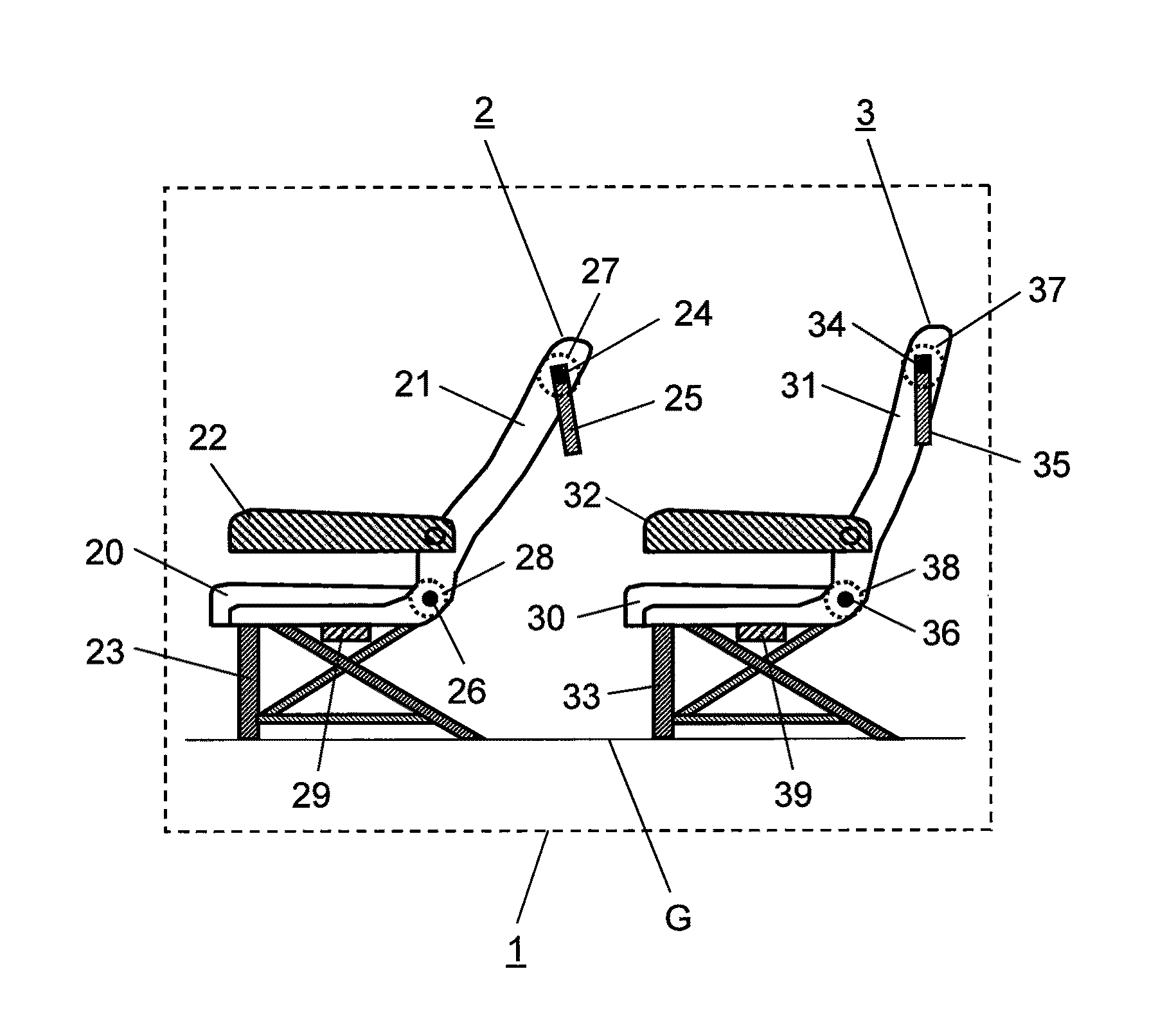
[0023]FIG. 1 is a schematic view showing a key structure of a seat row provided with image display devices according to the exemplary embodiment of this invention, and it is the basic structure illustrating components of seat row 1 represented by two adjoining seats among a group of seats provided with image display device 100 shown in FIG. 2.

[0024]Among a plurality of seat units arranged in a front-to-back direction on floor surface G, one seat unit 2 located in the nth position from the front end (referred to as “seat 2”, and this also applies to other seat units) comprises seating part 20, backrest 21, armrests 22 and legs 23. Backrest 21 is constructed reclinable in various angles about reclining shaft 26. Seat 2 is provided with image display panel 25 installed on the back of backrest 21 in a manner that a tilt angle is variable a...


PUM


Abstract

An image display device comprising a plurality of seats arranged at least in a front-to-back direction, each of the seats having a backrest of a variable angle, an image display panel installed on the back of each seat, an angle sensing unit for detecting an angle of the backrest of the seat, a tilt angle calculating unit for calculating a tilt angle of the image display panel based on an output data of the angle sensing unit related to each of two adjoining seats in the front-to-back direction, and a tilt controller unit for controlling the tilt angle of the image display panel according to an output data of the tilt angle calculating unit.

Description

[0001]THIS APPLICATION IS A U.S. NATIONAL PHASE APPLICATION OF PCT INTERNATIONAL APPLICATION PCT / JP2008 / 000541.TECHNICAL FIELD[0002]The present invention relates to an image display device having a function of automatically adjusting a tilt angle of an image display panel serving for a viewer in each seat inside a large transporting apparatus such as an aircraft and a train provided with a plurality of passenger seats having reclining angles of their backrests adjustable.BACKGROUND ART[0003]Image display devices hitherto installed on passenger seats of aircrafts, trains and the like are generally of a type having an image display panel, a tilt angle of which is manually adjustable so that the passenger watching the display adjusts the tilt angle of it with his hand.[0004]FIG. 6A and FIG. 6B show one example of such conventional image display devices installed on seats of an aircraft, a train or the like. FIG. 6A shows one aspect, for instance, wherein a tilt angle of an image displa...

Claims


Application Information

Patent Timeline
Patent Type & Authority Patents(United States)
IPC IPC(8): A47C7/62A47C15/00
CPCA47C7/62B60N2/22B60R11/0235B61D33/0007B64D11/0015G09F9/30G09F23/00B60R2011/0015B60R2011/0092G09F2023/005B64D11/00151B64D11/064
Inventor KUNOU, TADASHI
Owner PANASONIC CORP
Why Eureka
Try Eureka